Adjustable Flip Platform

- Designed for 90° Angular Adjustment
- Up to 180° Angular Adjustment in Certain Configurations
- Lockable Angular Position
- Compact Design with Various Mounting Options
FP90
Adjustable Flip Platform
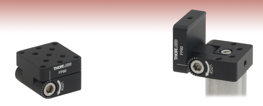
Flip Platform Mounted on a Ø1" Post and Locked at 90°

Please Wait

Click to Enlarge
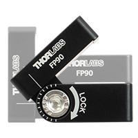
Figure 1.1 The adjustable flip platform can be set to a user-defined angle for components with specific mounting requirements. The engraved scale with 15° increments guides platform angle positioning.
Features
- 90° Angular Adjustment Range when Mounted Horizontally
- 180° Angular Adjustment Range when Mounted Vertically
- Side-Located Locking Cap Screw with 3/16" (5 mm) Hex
- 1.25" x 1.25" Mounting Platform with Eleven 8-32 (M4) Tapped Holes
- 8-32 (M4) Mounting Tap on the Side of Each Plate
- Four 8-32 Tapped Holes on the Bottom Plate for Additional Mounting Options
- Engraved Tick Marks Show 15° Increments
The Adjustable Flip Platform is designed to attach to the top of our Ø1/2" or Ø1" posts and provide flexible mounting options for components. The flip platform can be secured on the post using the #8 (M4) counterbore located in the center of the bottom plate, or the 8-32 (M4) tapped mounting hole on the side of either of the two plates. The 1.25" x 1.25" top plate features eleven 8-32 (M4) tapped holes for mounting components.
The top plate can be locked at any angle between 0° and 90° with respect to the optical table surface when mounted using the counterbore in the center of the bottom plate. When mounted using the 8-32 tapped hole on the side, the top plate can be adjusted between -90° and +90° with respect to the optical table surface. In order to lock the platform in place, tighten the cap screw on the side using a 3/16" (5 mm) balldriver or hex key. Test data for the effectiveness of the locking screw can be found in the Locking Torque tab.
The flip platform can be converted between a right- and left-handed setup. Simply remove the locking screw, separate the top and bottom plates, flip the bottom plate upside-down, and reassemble the flip platform. This allows the user to choose the direction from which the locking screw is accessed, in case one orientation better suits the experimental setup.
Thorlabs also offers post mounting angle blocks that can be used to place a mirror or other optical component at a fixed angle.

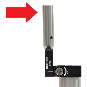
Figure 2.1 To test the locking torque of the flip platform, a force was applied to a post mounted on top of the top plate, as indicated by the red arrow. The force was increased until the locking screw could no longer hold the top plate in place.
The adjustable flip platform has undergone testing to determine the load bearing capacity of the flexure locking screw. The top and bottom plates of the platform were set at 90° with respect to one another. The plates were locked in place with varying amounts of torque applied to the locking screw, as shown in Table 2.2. The bottom plate was secured to a Ø1" post, and a Ø1/2" post was attached to the edge of the top plate. A horizontal force was applied to the post at a distance of 3" from the platform's pivot point. The force was increased until the locking screw could no longer hold the top plate in place. The torque values at which the locking screw failed are listed in Table 2.2.
| Table 2.2 Locking Torque Testing | |
|---|---|
| Torque Applied to Locking Screw (in-lb) |
Torque Required to Move Locked Platforma (in-lb) |
| 30 | 33 |
| 35 | 39 |
| 40 | 42 |
| 45 | 45 |
| Posted Comments: | |
| No Comments Posted |
 Products Home


 Adjustable Flip Platform