 Products Home / Lab Supplies / Light Accessories / Alignment Tools / Infrared Viewer Alignment Tools
Infrared Viewer Alignment Tools
- Detect Wavelengths from UV to IR
- Visualize Beams Not Visible Through Safety Glasses
- Visualize Diffuse Light Not Visible on Laser Viewing Cards
- Handheld or Post Mountable
VWR1B
(350 nm - 1300 nm)
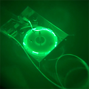
Viewing an IR Laser Beam with an IR Viewer


Please Wait
IR Viewers in Action


Features
- Observe Indirect Radiation of Infrared (IR) Lasers, Light Emitting Diodes (LEDs), Dye Lasers, and Other IR Sources
- Versions for 350 - 1300 nm (Item # VWR1B) or 350 - 1700 nm (Item # VWR2B)
- Lightweight: 0.4 kg
- 1/4"-20 Threaded Hole Allows Post Mounting
- Rechargeable via Micro-USB Charging Port (USB to Micro USB Cord Included)
- Excellent Resolution of 60 LP/mm
- View Continuous or Pulsed Laser Radiation
Applications
- Laser Alignment and Safety
- Examine Dirty and/or Damaged Optics in Situ
- Visualize Beam Size and Shape
- Identify Breaks or Light Leakage in a Fiber System
- Align Laser Cavities
- View Overlapping Spots in a Crystal
- Other IR Light Applications in Photonics, Biology, Agriculture, and Electronics
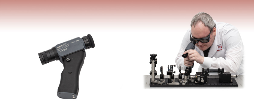
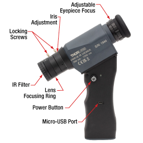
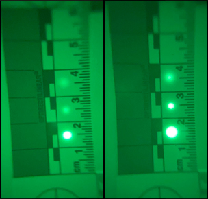
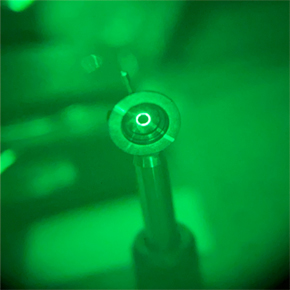
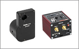
These Infrared (IR) Viewers are high-grade image converters designed to observe indirect radiation from infrared lasers, light emitting diodes (LEDs), and other IR sources. The VWR1B viewer can be used with sources that emit from 350 to 1300 nm, while the VWR2B viewer can be used with sources that emit from 350 to 1700 nm. These viewers have a large focal range, from less than a meter to infinity, which makes them ideal for a wide variety of applications. Images of the IR Viewer and the view through its scope during applications such as beam alignment, examining dirty optics, and identifying light leakage are shown to the right.
These IR viewers can be focused using an adjustable eyepiece focus and a lens focusing ring, both of which are lockable, to achieve a clear image. The brightness and depth of focus of the resulting image can be adjusted using the lockable iris. These IR viewers include a rechargeable battery with a micro-USB port for charging and will automatically power down after several minutes to preserve battery life. A USB-to-Micro-USB charging cord is included with the viewers; while a power supply is not included, our DS5 power supply is compatible with the viewers. The locations of the features of these IR viewers can be seen in the first image to the right. Magnets are included on the base of the IR viewers so that the viewers can stand upright on an optical table. For more information on the operation of these IR viewers, see the Operation tab.
Photosensitivity of IR Viewers
The minimum detectable signal for the IR viewers depends on:
- Power Density
- Wavelength of Incident Light
- Effective Aperture of the Objective Lens
- Distance Between Observed Target and the Viewer
- Time Duration of the Signal (Pulsed or Continuous)
- Reflectivity of the Diffusing Surface
- Sensitivity of the Human Eye to the IR Viewer Output
Listed below are the approximate minimum power densities required for observing an IR laser source with the IR viewers from a distance of one meter:
- 20 µW/cm2 for 1060 nm Source
- 500 µW/cm2 for 1300 nm Source
Please see the image gallery above and the Graphs tab for usage examples and data.
Click to Enlarge
Diagram of the interior of the IR Viewer showing photocathode, electrostatic lens, and phosphor screen.
Usage Tips
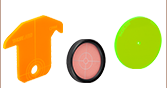
IR viewers are ideal for alignment of UV to IR laser beams and optical components in UV to IR systems. IR viewers can visualize beams that are not visible through required laser safety goggles. Paper cards or metal surfaces, like our iris diaphragms, work well when viewing reflected radiation. For some wavelength regions, viewing through an IR viewer using an IR card (like Item # VRC4) as the surface under illumination can provide additional sensitivity (this works especially well near 1550 nm).
To optimize the view through the IR viewer, we recommend looking first at a test target with good contrast. For example, a white piece of paper with thick black text that is well lit by visible and/or IR light should work well. While looking at the test target through the IR viewer from a distance that is roughly the same as that for your intended use, iterate between rotating the objective lens focusing ring and the eyepiece focusing ring until the text appears in focus (see the first image to the right for the focusing ring locations). Typically after this initial alignment only the objective lens focusing ring will need to be tuned for fine focus control. However, if multiple users with different eyesight are using the IR viewer, the eyepiece focusing ring may also need to be adjusted for each individual. If further adjustment of the eyepiece focusing ring is unable to bring the object into focus, then the initial focusing procedure should be repeated.
How Does it Work?
IR viewers focus emitted or reflected light from a chosen subject into an evacuated tube with a photocathode where a photoelectron image is generated by the incident radiation. The generated photoelectrons are accelerated by a 16 - 18 kV voltage when powered. These accelerated photoelectrons are directed toward the output phosphor screen. When they hit the phosphor, the incident photoelectrons cause it to glow. The photoelectrons generated by the photocathode and their subsequent acceleration by a strong electric field is known as an electrostatic lens. Photoelectrons generated in different locations by the incident radiation arrive at the phosphor in different locations, creating a visible image of the incident radiation. The fluorescent green light output (550 nm) from the excitation of the phosphor can be observed via an adjustable eyepiece lens and is independent of the wavelength of the incident radiation.
| Item # | VWR1B | VWR2B |
|---|---|---|
| Spectral Sensitivity | 350 - 1300 nm | 350 - 1700 nm |
| Resolution (Center) | 60 LP/mm | |
| Field of View | 40° | |
| Magnification | 1X | |
| Objective Lens | F1.4/25 mm | |
| Adjustable Iris | Included | |
| Focus | <0.1 m to Infinity | |
| Charging Port | 5 V Micro-USB | |
| Non-Uniformity of Screen | <20% | |
| Non-Uniformity of Response | <15% | |
| Distortion of Image | <18% | |
| Battery Life (Continuous) | 50 hours | |
| Weight | 0.4 kg | |
| Dimensions | 153.0 mm - 157.1 mm x 172.9 mm x 51.0 mm (6.02" - 6.18" x 6.81" x 2.01") |
|
| Temperature Range | -10 °C to 40 °C | |
| Mounting Threada | 1/4"-20 Internal Thread | |

Click to Enlarge
This plot shows the typical spectral sensitivity for each IR viewer. This data is for reference only and actual performance may vary.

Click to Enlarge
This plot shows the typical power density required to see IR laser light with the IR viewers. This data is for reference only and actual performance may vary.

Insights into Aligning a Laser Beam
When installing a laser in an optical setup, it is good practice to start by leveling and orienting its beam so that it travels along a well-defined path. When the beam is prepared this way, not only is it easier to then divert the beam and route it through the optical elements in the system, but the results provided by tuning the system's alignment are more predictable and repeatable. The following sections describe how to:
- Level and Align the Laser Beam's Pointing Angle
- Divert the Beam and Align it to Follow a Desired Path
Click here for more Insights about lab practices and equipment.
Level and Align the Laser Beam's Pointing Angle
0:00 - Introduction
1:25 - Level and Align the Laser Beam's Pointing Angle
4:09 - Divert the Beam and Align it to Follow a Desired Path

Click to Enlarge
Figure 2: The beam can be aligned to travel parallel to a line of tapped holes in the optical table. The yaw adjustment on the kinematic mount adjusts the beam angle, so that the beam remains incident on the ruler's vertical reference line as the ruler slides along the line of tapped holes.

Click to Enlarge
Figure 1: Leveling the beam path with respect to the surface of an optical table requires using the pitch adjustment on the kinematic laser mount (Figure 2). The beam is parallel to the table's surface when measurements of the beam height near to (left) and far from (right) the laser's front face are equal.
Pitch (tip) and yaw (tilt) adjustments provided by a kinematic mount can be used to make fine corrections to a laser beam's angular orientation or pointing angle. This angular tuning capability is convenient when aligning a collimated laser beam to be level with respect to a reference plane, such as the surface of an optical table, and when aligning with respect to a particular direction in that plane, such as along a line of tapped holes in the table.
Before Using the Mount's Adjusters
First, rotate each adjuster on the kinematic mount to the middle of its travel range. This reduces the risk of running out of adjustment range, and the positioning stability is frequently better when at the center of an adjuster's travel range.
Then, make coarse corrections to the laser's height, position, and orientation. This can be done by adjusting the optomechanical components, such as a post and post holder, supporting the laser. Ensure all locking screws are tightened after the adjustments are complete.
Level the Beam Parallel to the Table's Surface
Leveling the laser beam is an iterative process that requires an alignment tool and the fine control provided by the mount's pitch adjuster.
Begin each iteration by measuring the height of the beam close to and far from the laser (Figure 1). A larger distance between the two measurements increases accuracy. If the beam height at the two locations differs, place the ruler in the more distant position. Adjust the pitch on the kinematic mount until the beam height at that location matches the height measured close to the laser. Iterate until the beam height at both positions is the same.
More than one iteration is necessary, because adjusting the pitch of the laser mount adjusts the height of the laser emitter. In the video for example, the beam height close to the laser was initially 82 mm, but it increased to 83 mm after the pitch was adjusted during the first iteration.
If the leveled beam is at an inconvenient height, the optomechanical components supporting the laser can be adjusted to change its height. Alternatively, two steering mirrors can be placed after the laser and aligned using a different procedure, which is detailed in the section. Steering mirrors are particularly useful for adjusting beam height and orientation of a fixed laser.
Orient the Beam Along a Row of Tapped Holes
Aligning the beam parallel to a row of tapped holes in the table is another iterative process, which requires an alignment tool and tuning of the mount's yaw adjuster.
The alignment tool is needed to translate the reference line provided by the tapped holes into the plane of the laser beam. The ruler can serve as this tool, when an edge on the ruler's base is aligned with the edges of the tapped holes that define the line (Figure 2).
The relative position of the beam with respect to the reference line on the table can be evaluated by judging the distance between the laser spot and vertical reference feature on the ruler. Vertical features on this ruler include its edges, as well as the columns formed by different-length rulings. If these features are not sufficient and rulings are required, a horizontally oriented ruler can be attached using a BHMA1 mounting bracket.
In the video, when the ruler was aligned to the tapped holes and positioned close to the laser, the beam's edge and the ends of the 1 mm rulings coincided. When the ruler was moved to a farther point on the reference line, the beam's position on the ruler was horizontally shifted. With the ruler at that distant position, the yaw adjustment on the mount was tuned until the beam's edge again coincided with the 1 mm rulings. The ruler was then moved closer to the laser to observe the effect of adjusting the mount on the beam's position. This was iterated as necessary.
Divert the Beam and Align it to Follow a Desired Path
The first steering mirror reflects the beam along a line that crosses the new beam path. A second steering mirror is needed to level the beam and align it along the new path. The procedure of aligning a laser beam with two steering mirrors is sometimes described as walking the beam, and the result can be referred to as a folded beam path. In the example shown in the video above, two irises are used to align the beam to the new path, which is parallel to the surface of the optical table and follows a row of tapped holes.

Click to Enlarge
Figure 3: The beam reflected from Mirror 1 will be incident on Mirror 2, if Mirror 1 is rotated around the x- and y-axes by angles θ and ψ, respectively. Both angles affect each coordinate (x2 , y2 , z2 ) of Mirror 2's center. Mirror 1's rotation around the x-axis is limited by the travel range of the mount's pitch (tip) adjuster, which limits Mirror 2's position and height options.

Click to Enlarge
Figure 5: The adjusters on the second kinematic mirror are used to align the beam on the second iris.

Click to Enlarge
Figure 4: The adjusters on the first kinematic mirror mount are tuned to position the laser spot on the aperture of the first iris.
Setting the Heights of the Mirrors
The center of the first mirror should match the height of the input beam path, since the first mirror diverts the beam from this path and relays it to a point on the second mirror. The center of the second mirror should be set at the height of the new beam path.
Iris Setup
The new beam path is defined by the irises, which in the video have matching heights to ensure the path is level with respect to the surface of the table. A ruler or calipers can be used to set the height of the irises in their mounts with modest precision.
When an iris is closed, its aperture may not be perfectly centered. Because of this, switching the side of the iris that faces the beam can cause the position of the aperture to shift. It is good practice to choose one side of the iris to face the beam and then maintain that orientation during setup and use.
Component Placement and Coarse Alignment
Start by rotating the adjusters on both mirrors to the middle of their travel ranges. Place the first mirror in the input beam path, and determine a position for the second mirror in the new beam path (Figure 3). The options are notably restricted by the travel range of the first mirror mount's pitch (tip) actuator, since it limits the mirror's rotation (θ ) around its x-axis. In addition to the pitch, the yaw (tilt) of the first mirror must also be considered when choosing a position
After placing the second mirror on the new beam path, position both irises after the second mirror on the desired beam path. Locate the first iris near the second mirror and the second iris as far away as possible.
While maintaining the two mirrors' heights and without touching the yaw adjusters, rotate the first mirror to direct the beam towards the second mirror. Adjust the pitch adjuster on the first mirror to place the laser spot near the center of the second mirror. Then, rotate the second mirror to direct the beam roughly along the new beam path.
First Hit a Point on the Path, then Orient
The first mirror is used to steer the beam to the point on the second mirror that is in line with the new beam path. To do this, tune the first mirror's adjusters while watching the position of the laser spot on the first iris (Figure 4). The first step is complete when the laser spot is centered on the iris' aperture.
The second mirror is used to steer the beam into alignment with the new beam path. Tune the adjusters on the second mirror to move the laser spot over the second iris' aperture (Figure 5). The pitch adjuster levels the beam, and the yaw adjuster shifts it laterally. If the laser spot disappears from the second iris, it is because the laser spot on the second mirror has moved away from the new beam path.
Tune the first mirror's adjusters to reposition the beam on the second mirror so that the laser spot is centered on the first iris' aperture. Resume tuning the adjusters on the second mirror to direct the laser spot over the aperture on the second iris. Iterate until the laser beam passes directly through the center of both irises, as shown in the video. If any adjuster reaches, or approaches, a limit of its travel range, one or both mirrors should be repositioned and the alignment process repeated.
If a yaw axis adjuster has approached a limit, note the required direction of the reflected beam and then rotate the yaw adjuster to the center of its travel range. Turn the mirror in its mount until the direction of the reflected beam is approximately correct. If the mirror cannot be rotated, reposition one or both mirrors to direct the beam roughly along the desired path. Repeat the alignment procedure to finely tune the beam's orientation.
If a pitch axis adjuster has approached a limit, either increase the two mirrors' separation or reduce the height difference between the new and incident beam paths. Both options will result in the pitch adjuster being positioned closer to the center of its travel range after the alignment procedure is repeated.
Laser Safety and Classification
Safe practices and proper usage of safety equipment should be taken into consideration when operating lasers. The eye is susceptible to injury, even from very low levels of laser light. Thorlabs offers a range of laser safety accessories that can be used to reduce the risk of accidents or injuries. Laser emission in the visible and near infrared spectral ranges has the greatest potential for retinal injury, as the cornea and lens are transparent to those wavelengths, and the lens can focus the laser energy onto the retina.
 |
 |
 |
 |
 |
 |
 |
 |
 |
Safe Practices and Light Safety Accessories
- Laser safety eyewear must be worn whenever working with Class 3 or 4 lasers.
- Regardless of laser class, Thorlabs recommends the use of laser safety eyewear whenever working with laser beams with non-negligible powers, since metallic tools such as screwdrivers can accidentally redirect a beam.
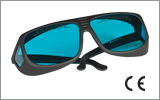
- Laser goggles designed for specific wavelengths should be clearly available near laser setups to protect the wearer from unintentional laser reflections.
- Goggles are marked with the wavelength range over which protection is afforded and the minimum optical density within that range.
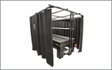
- Laser Safety Curtains and Laser Safety Fabric shield other parts of the lab from high energy lasers.
- Blackout Materials can prevent direct or reflected light from leaving the experimental setup area.
- Thorlabs' Enclosure Systems can be used to contain optical setups to isolate or minimize laser hazards.
- A fiber-pigtailed laser should always be turned off before connecting it to or disconnecting it from another fiber, especially when the laser is at power levels above 10 mW.
- All beams should be terminated at the edge of the table, and laboratory doors should be closed whenever a laser is in use.
- Do not place laser beams at eye level.
- Carry out experiments on an optical table such that all laser beams travel horizontally.
- Remove unnecessary reflective items such as reflective jewelry (e.g., rings, watches, etc.) while working near the beam path.
- Be aware that lenses and other optical devices may reflect a portion of the incident beam from the front or rear surface.
- Operate a laser at the minimum power necessary for any operation.
- If possible, reduce the output power of a laser during alignment procedures.
- Use beam shutters and filters to reduce the beam power.
- Post appropriate warning signs or labels near laser setups or rooms.
- Use a laser sign with a lightbox if operating Class 3R or 4 lasers (i.e., lasers requiring the use of a safety interlock).
- Do not use Laser Viewing Cards in place of a proper Beam Trap.
Laser Classification
Lasers are categorized into different classes according to their ability to cause eye and other damage. The International Electrotechnical Commission (IEC) is a global organization that prepares and publishes international standards for all electrical, electronic, and related technologies. The IEC document 60825-1 outlines the safety of laser products. A description of each class of laser is given below:
| Class | Description | Warning Label |
|---|---|---|
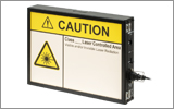
| 1 | This class of laser is safe under all conditions of normal use, including use with optical instruments for intrabeam viewing. Lasers in this class do not emit radiation at levels that may cause injury during normal operation, and therefore the maximum permissible exposure (MPE) cannot be exceeded. Class 1 lasers can also include enclosed, high-power lasers where exposure to the radiation is not possible without opening or shutting down the laser. |  |
| 1M | Class 1M lasers are safe except when used in conjunction with optical components such as telescopes and microscopes. Lasers belonging to this class emit large-diameter or divergent beams, and the MPE cannot normally be exceeded unless focusing or imaging optics are used to narrow the beam. However, if the beam is refocused, the hazard may be increased and the class may be changed accordingly. |  |
| 2 | Class 2 lasers, which are limited to 1 mW of visible continuous-wave radiation, are safe because the blink reflex will limit the exposure in the eye to 0.25 seconds. This category only applies to visible radiation (400 - 700 nm). |  |
| 2M | Because of the blink reflex, this class of laser is classified as safe as long as the beam is not viewed through optical instruments. This laser class also applies to larger-diameter or diverging laser beams. |  |
| 3R | Class 3R lasers produce visible and invisible light that is hazardous under direct and specular-reflection viewing conditions. Eye injuries may occur if you directly view the beam, especially when using optical instruments. Lasers in this class are considered safe as long as they are handled with restricted beam viewing. The MPE can be exceeded with this class of laser; however, this presents a low risk level to injury. Visible, continuous-wave lasers in this class are limited to 5 mW of output power. |  |
| 3B | Class 3B lasers are hazardous to the eye if exposed directly. Diffuse reflections are usually not harmful, but may be when using higher-power Class 3B lasers. Safe handling of devices in this class includes wearing protective eyewear where direct viewing of the laser beam may occur. Lasers of this class must be equipped with a key switch and a safety interlock; moreover, laser safety signs should be used, such that the laser cannot be used without the safety light turning on. Laser products with power output near the upper range of Class 3B may also cause skin burns. |  |
| 4 | This class of laser may cause damage to the skin, and also to the eye, even from the viewing of diffuse reflections. These hazards may also apply to indirect or non-specular reflections of the beam, even from apparently matte surfaces. Great care must be taken when handling these lasers. They also represent a fire risk, because they may ignite combustible material. Class 4 lasers must be equipped with a key switch and a safety interlock. |  |
| All class 2 lasers (and higher) must display, in addition to the corresponding sign above, this triangular warning sign. |  |
|
| Posted Comments: | |
Frank van Mourik
(posted 2023-11-11 15:32:23.627) Received one week ago
Was clearly defective, top left corner of the Phosphor screen was not working like it had a large ink blob on it.
Mailed to Thorlabs Germany immediately, no reply so far.
But, to be honest, the part that was working is also not upto the standard, and I would not advise anyone to buy this product.
The lens on it is not suited for the application, it is for small CCD sensors. On the larger photocathode the distortion would make me seasick if I had to work with it
and the controlls for the focussing are simply only suited for small childrens fingers.
I would advise you to have this device tested by Sterling B. and ask his opinion.
I go back to the 50 years old design of FJW that is even cheaper to begin with...
Best regards,
Frank cdolbashian
(posted 2023-11-16 04:17:43.0) Thank you for reaching out to us with this valuable feedback. As this is a new item, this type of feedback is welcome! I have contacted you directly to discuss your experience with our product and assist you in facilitating a return. |
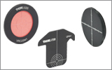
| Alignment Disks, Laser Viewing Cards, and IR Viewers Selection Guide | ||||||
|---|---|---|---|---|---|---|
| (Click Representative Drawing for Details; Not to Scale) |
 |
 |
|
 |
 |
 |
| Wavelengths | Ø1/2" Unmounted Disk | Ø1" Unmounted Disk | Threaded Disk | Alignment Plate with Disk for 30 mm Cage System | Viewing Cards | IR Viewers |
| 250 - 540 nm | VRC1D05 | VRC1D1 | VRC1SM05 (SM05 Threading) |
VRC1CPT | VRC1 | - |
| VRC1SM1 (SM1 Threading) |
||||||
| VRC1SM2 (SM2 Threading) |
||||||
| 350 - 1300 nm | - | - | - | - | - | VWR1B |
| 350 - 1700 nm | - | - | - | - | - | VWR2B |
| 400 - 640 nm 800 - 1700 nm |
VRC2D05 | VRC2D1 | VRC2SM05 (SM05 Threading) |
VRC2CPT | VRC2 | - |
| VRC2RMS (RMS Threading) |
||||||
| VRC2SM1 (SM1 Threading) |
||||||
| VRC2SM2 (SM2 Threading) |
||||||
| 700 - 1400 nm | - | - | - | - | VRC5 | - |
| 790 - 840 nm, 870 - 1070 nm, 1500 to 1590 nm |
VRC4D05 | VRC4D1 | VRC4SM05 (SM05 Threading) |
VRC4CPT | VRC4 | - |
| VRC4SM1 (SM1 Threading) |
||||||
| VRC4SM2 (SM2 Threading) |
||||||
| 1500 - >13 200 nm | - | - | VRC6SM1 (SM1 Threading) |
VRC6SCPT | VRC6S VRC6H |
- |
