High-Power Xenon Light Sources with Liquid Light Guides

- High-Power Light Sources with 380 - 780 nm Wavelength Range
- Ø3 mm or Ø5 mm LLG-Coupled Output
- External Power Adjustment or Shutter Control
- Lamp Lifespan: 1000 Hours (Average)
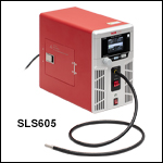
SLS605
High-Power Xenon Light Source with
Ø5 mm LLG-Coupled Output
The settings and controls on the front panel are also accessible remotely via the software GUI.
SLS600B
Replacement Xenon Arc Lamp

Please Wait
| Key Specificationsa | ||
|---|---|---|
| Item # | SLS603 | SLS605 |
| Wavelength Range | 380 - 780 nm | |
| Color Temperatureb | 6000 K | |
| Color Rendering Indexb | >95 | |
| Typical Output Powerc | >7 W | >15 W |
| Output Coupling | Ø3 mm LLG | Ø5 mm LLG |
| Included Liquid Light Guide | LLG03-4H | LLG05-4H |
| Modulation Time (Typ.) | 3 seconds (40 - 60%) 8 seconds (10 - 90%) 11 seconds (0.1 - 100%) |
|
| Shutter Frequency (Max) | 1 Hz | |
| Output Power Stabilityd | ≤0.3% | |
| Lamp Electrical Power | 300 W | |
| Lamp Lifespan (Avg.)e | 1000 Hours | |
Click to Enlarge
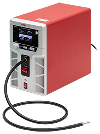
These high-power light sources incorporate xenon short-arc lamps and feature LLG-coupled outputs.
Click to Enlarge
Click Here for Raw Data
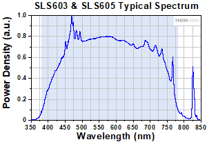
The typical spectral power distribution for the SLS603 & SLS605 High-Power Light Sources measured prior to the LLG. The blue-shaded region indicates the -10 dB power operating wavelength range.
Features
- Output Spectrum: 380 to 780 nm
- Liquid Light Guide (LLG) Coupled Output
- Compatible LLG Included with Each Source
- Input Tip of LLG is Cooled Using Thermoelectric Coolers (TECs) to Extend LLG's Lifetime
- Independent Shutter Toggled via Automated and/or Manual Controls
- Location-Specific Power Cord Included
Optional Accessories
- Replacement Lamps
- Collimating Adapters for Microscopy
- Additional LLGs
Thorlabs' SLS603 & SLS605 High-Power Xenon Arc Light Sources with Liquid Light Guides provide stable illumination from 380 to 780 nm. The emitted light is coupled into a liquid light guide (LLG), which homogenizes the transmitted bulb emission and produces a uniform output light field. The broad output spectrum extends down to 380 nm and overlaps with the common DAPI, FITC, and TRITC filter sets used in biological imaging, making these high-power sources well suited for fluorescence microscopy. In addition, the wide spectrum of these sources is important for hyperspectral imaging, endoscopy, and other lighting and inspection applications.
The front panel of each high-power light source features controls and an LCD screen for full control of the source power, light intensity, shutter, and enabling or disabling external trigger inputs. The back panel features BNC connectors for external triggering and power modulation inputs, as well as a monitor output and USB port for computer control. The software GUI available for download on the Software tab offers full remote control mirroring the functionality available on the front panel. Command line operation is also available using USB connectivity and a terminal emulator or a user-created program.
Liquid Light Guides
The SLS603 and SLS605 high-power light sources are designed to couple light from the xenon lamp into the included LLG with a Ø3 mm or Ø5 mm core, respectively (the sources will not operate without a compatible LLG properly inserted). The advantages of LLGs include a transmitted beam free of dead spots, flexibility that allows them to be coiled, a large core size, and a high numerical aperture. Please see the LLGs tab for additional information. The Ø3 mm light guide provides a beam with higher brightness, while higher total power is coupled into the Ø5 mm LLG. It is possible to focus the beam from the Ø3 mm guide into a smaller spot, and under certain conditions this smaller core diameter may result in more power being coupled into a microscope. Coupling light from the endface of the LLG to a variety of microscopes can be enabled by using the collimation adapters available below. Thorlabs also offers LLG-to-SM1 adapters for both Ø3 mm and Ø5 mm core LLGs (Item #s AD3LLG and AD5LLG).
These high-power light sources use thermoelectric coolers to control the temperature of the LLG tip closest to the bulb, which extends the lifetime of the LLG. Also, the lamp in these sources is designed for continuous operation. It is advisable to refrain from frequent cycling of the lamp between ON and OFF states, as this may significantly reduce its lifespan. For optimal performance, it is recommended to allow 45 minutes to one hour for the lamp to reach thermal equilibrium after being switched on. It is recommended to use the shutter to turn the light output off and on instead of frequently powering the lamp off and back on. Closing the shutter during periods when the output emission of the light source is not needed will also extend the lifetime of the LLG, because this reduces its exposure to the UV radiation from the lamp. Accumulated exposure to the UV portion of the lamp's spectrum increases the attenuation of the LLG, and the LLG should be replaced when transmission levels drop below those required by the application. We recommend the LLGs offered below, which differ from our standard LLG offerings only in that these have a yellow band that acts as a visual guide that indicates when the LLG is correctly installed in the LLG Port of the light source.
| Item # | SLS603 | SLS605 |
|---|---|---|
| Wavelength Range | 380 - 780 nm | |
| Color Temperaturea | 6000 K | |
| Color Rendering Indexa | >95 | |
| Typical Output Powerb | >7 W | >15 W |
| Output Coupling | Ø3 mm LLG | Ø5 mm LLG |
| Included Liquid Light Guide (LLG) | LLG03-4H | LLG05-4H |
| Modulation Time (Typ.) | 3 seconds (40 - 60%) 8 seconds (10 - 90%) 11 seconds (0.1 - 100%) |
|
| Shutter Frequency (Max) | 1 Hz | |
| Output Power Stabilityc | ≤0.3% | |
| Lamp Electrical Power | 300 W | |
| Lamp Lifespan (Average)d | 1000 Hours | |
| Operating Temperature Range | 0 to 45 °C | |
| Storage Temperature Range | -15 to 70 °C | |
| Power Supply | 100 - 240 VAC, 50 - 60 Hz | |
| Dimensions (L x W x H) | 287.6 mm x 149.6 mm x 259.3 mm (11.32" x 5.89" x 10.21") |
|
| Mass (Weight) | 6.2 kg (13.7 lbs) | |
Click to Enlarge
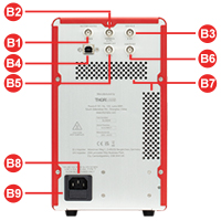
SLS605 Back Panel
Click to Enlarge
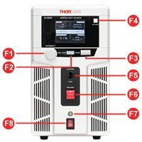
SLS605 Front Panel
| Front Panel | Back Panel | ||
|---|---|---|---|
| Callout | Description | Callout | Description |
| F1 | Light Intensity Adjustment Knob | B1 | BNC Port for Shutter Control: 5 V CMOS |
| F2 | Lamp On/Off Button w/LED Indicator | B2 | BNC Port for Trigger In: 5 V CMOS |
| F3 | Shutter Control Button | B3 | BNC Port for Analog In: 0 to 5 V |
| F4 | Control Mode Switching Button | B4 | USB Port |
| F5 | Liquid Light Guide Port | B5 | BNC Port for Trigger Out: 5 V CMOS |
| F6 | Liquid Light Guide Release Switch | B6 | BNC Port for Analog Out: 0 to 5 V |
| F7 | Light Source State Indicator LED | B7 | Exhaust Vents |
| F8 | Power Switch | B8 | AC Power Inlet |
| B9 | Fuse Drawer | ||
- Power off the light source and disconnect the LLG and power cord. Wait for at least 30 minutes for the lamp to cool down.
- Pull the latch on the side of the device to open the hatch and gain access to the lamp, as shown below in Figure 1.
- Remove the plastic block located next to the reflector of the lamp. It shouldn’t need to be forced. Insert the short arm of a 1.5 mm or 3/32" hex key into the slot on the side of the plastic block and wiggle it back and forth to slide it out, as shown in Figure 2.
- Unplug the lamp connector by holding down the two clips and pulling it away from its socket, as shown in Figure 3.
- Push the plastic lamp holder all the way left until it reaches the back of the housing, as shown in Figure 4.
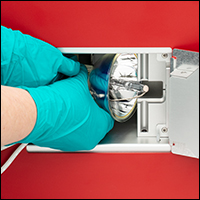
- Hold the ceramic base of the lamp back with one hand and carefully remove the lamp with the other, as shown in Figure 5. Be careful with the lamp anode and ensure it does not contact the metal housing.
- Unpack the new lamp. Hold the lamp base with one hand and carefully insert the lamp with the other hand. Be careful with the lamp anode and ensure it does not touch the housing’s metal interior.
- Once the new lamp is in place, release the lamp base to secure the new lamp.
- Reinsert the plastic block.
- Plug the lamp connector into the socket. Please be aware that the connector should be oriented such that the end with the ridge indicator is at upper position, as shown in Figure 3.
- Close the hatch on the side to complete the lamp replacement.
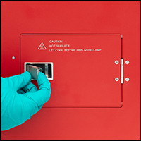
Click to Enlarge
Figure 1: Open the side hatch.
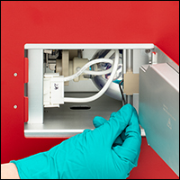
Click to Enlarge
Figure 2: Remove the plastic lamp retention block.
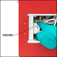
Click to Enlarge
Figure 3: Unplug the lamp connector. When reconnecting, ensure the plug is oriented with the indicator at the top.
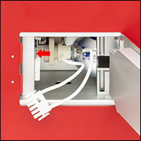
Click to Enlarge
Figure 4: Push the plastic lamp holder towards the back of the housing.
Click to Enlarge
Figure 5: Use both hands to carefully remove the lamp, ensuring the front tip of the lamp doesn't contact the housing.
Click to Enlarge
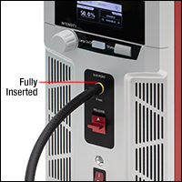
As shown above, the LLG is correctly installed when the majority of the marking ring is within the LLG port.
Liquid Light Guides for SLS603 & SLS605 Light Sources
The liquid cores of LLGs gradually become less transmissive with increasing exposure to UV light. As the xenon lamp spectrum extends into the UV, LLGs used to transmit light from these light sources will gradually become more absorptive with use. When the transmission properties of an LLG drops below usable levels, the LLG should be replaced. This will occur before the xenon lamp reaches its end-of-life. Closing the shutter during periods when the output emission of the light source is not needed will extend the lifetime of the LLG by blocking the coupling of the lamp's light into the LLG.
The dust cap on the output end of the LLG may burn if exposed to the intense light emitted by the LLG. To protect the LLG, and for safety, remove the dust cap before powering on the light source.
Installing and Removing a Liquid Light Guide
While all of Thorlabs' standard Ø3 mm (Ø5 mm) liquid light guides are compatible with the SLS603 (SLS605) light source, the LLG03-4H and LLG3-xH (LLG05-4H and LLG5-xH) LLGs are recommended. These LLGs each feature a yellow band near one end that acts as a visual indicator to help the user determine when the LLG is properly seated in the light source. When an LLG without the yellow band is used with these sources, it can be difficult to know when the LLG is correctly installed in the light source.
To insert the LLG, slide it into the LLG port as shown in the photo to the right. The LLG is fully inserted when the majority of the yellow marking ring is within the LLG port. To remove the LLG, press up on the Release switch and pull out the LLG. The light sources detect when an LLG is installed in the LLG Port. If there is no LLG present, the light source closes the shutter, and the shutter cannot be opened until an LLG is in place. This protects the user from exposure to the intense light emitted by the source.
To protect the tips of the LLGs from damage and to keep them as clean as possible, cover exposed LLG tips with their dust covers. Ensure that the tip of the LLG is free of grease, dust, and other contaminants before inserting it into the light source. For information on how to clean the tip, see the Cleaning section below.
Liquid Light Guide Overview
Click to Enlarge
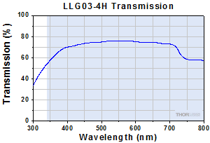
Figure 4: Plotted are typical transmission data for a Ø3 mm core, 4' long LLG, with the recommended operation wavelength range shaded blue. As a function of length, only minimal variations (<2.3%) are expected between our 4' (1.2 m), 6' (1.8 m), and 8' (2.4 m) long liquid light guides.
Click to Enlarge
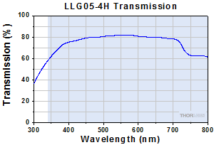
Figure 5: Plotted are typical transmission data for a Ø5 mm core, 4' long LLG, with the recommended operation wavelength range shaded blue. As a function of length, only minimal variations (<2.3%) are expected between 4' (1.2 m), 6' (1.8 m), and 8' (2.4 m) long liquid light guides.
A variety of applications benefit from the heat and vibration isolation achieved by routing the optical power output by a light source from a distant location to where it is needed. The SLS603 and SLS605 light souces have been designed to accept liquid light guides (LLGs) with Ø3 mm and Ø5 mm cores, respectively. LLGs are flexible light pipes fabricated from a polymer tube filled with a transparent, non-toxic, and non-flammable liquid. The tips of the tube are sealed with fused silica caps, which also act as optical end faces. Transmission through the LLG homogenizes the light field across the diameter of the core, which produces an output beam with uniform intensity. The many advantages of pairing an LLG with a high-power and broadband light source include:
- A Homogenous Transmitted Beam Free of the Dead Spots that Characterize the Light Field from a Silica Fiber Bundle
- The Ability to Coil and Arrange the LLGs, in Contrast to Silica Rods of Comparable Diameters that Break if Bent
- The Large Core Size and High Numerical Aperture of the LLG
- Excellent Transmission over the Entire Visible Spectral Range (Figures 4 and 5)
When used with the SLS603 and SLS605 light sources, the gasket of the LLG should not exceed 45 °C for long durations and 60 °C for durations of less than an hour. The gasket is indicated by the change in the fitting from chrome metal to a black color, as shown in the figure to the lower right. These LLGs are designed to operate at temperatures between -5 °C to 35 °C. The SLS603 and SLS605 light sources protect the LLG against excessive temperatures by monitoring the temperature of the tip of the LLG closest to the bulb, cooling the tip as required using a combination of thermoelectric coolers and fans, and powering down the light source if necessary. At higher temperatures, bubbles form in the liquid, which degrades the transmission properties of the LLG. If the temperature of gasket is between 45 °C to 60 °C for less than an hour, the bubbles can be reabsorbed by the liquid if the LLG is allowed to cool. We recommended a cool-down time of no less than 30 minutes. If the temperature of the gasket exceeds 60 °C, the LLG can be permanently damaged; the bubbles in the liquid will have a severe negative impact on the transmission properties of the LLG, and these high temperatures can also cause structural damage by degrading the seals between the various structural components of the guide.
LLGs, while flexible, also posses minimum bend radii. See the table below for the minimum bend radii of these LLGs. The tubes will develop permanent kinks if forced into a bend tighter than the minimum specification.
Reduction in Transmission with Exposure to Ultraviolet Light: The liquid in LLGs gradually becomes less transmissive with increasing exposure to UV light. As the xenon lamp spectrum extends into the UV, the LLGs used with SLS603 and SLS605 light sources will gradually become more absorptive with use. When the transmission properties drop below usable levels, the LLG should be replaced.
Cleaning the Optical End Faces of Liquid Light Guides: The fused silica, PTFE, and metal (either aluminum, chrome plated brass, or stainless steel) materials composing LLGs are resistant to common cleaning solvents; however, the tips of the LLGs should not be submerged in solvent, and neither should a heavily soaked cleaning pad be applied to the tip. Saturating the tip with solvent can result in the solvent penetrating the seal between the silica end face and the polymer tube and damaging the guide. If debris cannot be removed from the end face by wiping it with solvent, a razor blade, handled gently, can be used to clean the tip. If a razor blade is used, ensure that it does not chip the edge of the fused silica glass end face.
Liquid Light Guide Dimensions and Minimum Bend Radius:
| Active Core Diameter | Standard End Fittings | Protective Sleeve | Min Bend Radius | |||
|---|---|---|---|---|---|---|
| d0 | d1 | l1 | d2 | l2 | d3 | - |
| Ø3 mm | Ø5 +0/-0.1 mm | 20 ± 0.1 mm | Ø9 ± 0.1 mm | 24 ± 0.1 mm | Ø7 ± 0.1 mm | 40 mm |
| Ø5 mm | Ø7 +0/-0.1 mm | 20 ± 0.1 mm | Ø10 ± 0.1 mm | 24 ± 0.1 mm | Ø9.5 ± 0.1 mm | 60 mm |
The drawing and photograph below illustrate the dimensions given in the table above. 180 ± 1° indicates the flatness tolerence between the metal and black material in the segment labled l2.
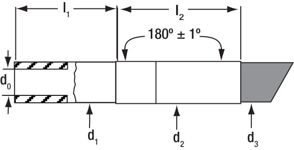 Figure 6: Diagram of an LLG Tip, with End Face at Left
Figure 7: End portion of an LLG with Key Dimensions Labeled.
| Recommended System Requirements | |
|---|---|
| Operating System | Windows® 7 SP1 (32-Bit, 64-Bit) with KB3020369 and KB3125574; Windows 10 (32-Bit, 64-Bit); Windows 11 (64-Bit) |
| Processor (CPU) | 1 GHz or Higher |
| Memory (RAM) | 2 GB |
| Hard Drive | 25 MB (Min) of Available Disk Space |
| Interface | Free USB 2.0 Port |
Software
Version 1.0.0
This software package provides a GUI to control the SLS603 & SLS605 Light Sources. To download, click the button below.
SLS60x GUI Software
The SLS60x software GUI’s controls duplicate most front panel functions, including intensity adjustment, turning the light source on/off, opening and closing the shutter, and activating/deactivating the ports on the back panel.
| Posted Comments: | |
| No Comments Posted |
Below is a selection guide for all of our white-light, broadband, lamp-based light sources. In addition to these sources, Thorlabs also offers unmounted white-light LEDs, white-light mounted LEDs, white-light fiber-coupled LEDs, and high-powered, white-light Solis® LEDs.
| Broadband Light Source Selection Guide | ||||||||||
|---|---|---|---|---|---|---|---|---|---|---|
| Item # | (Click to Enlarge; Not to Scale) |
Emitter Type | Wavelength Range (Click for Plot) |
Output Coupling | Output Power | Lamp Electrical Power |
Color Temperature |
Lamp Lifetime |
Replacement Lamp |
|
| SLS204 | Deuterium | 200 - 700 nm | Free Space or Fiber Coupled (SMA) |
2 mWa 0.1 mWb (Typ.) |
30 W | N/A | 2000 hc | SLS254B | ||
| SLS205 | Xenon Arc | 240 - 1200 nm | Free Space or Fiber Coupled (SMA) |
290 mWa 5 mWd (Typ.) |
75 W | 5800 Ka 5400 Kd |
2000 hc | SLS255B | ||
| SLS401 | Xenon Arc | 240 - 2400 nm | Free Spacee | >1.3 Wa | 150 W | 5800 K | 2000 hc | SLS401Bf or SLS402B |
||
| SLS402 | Mercury-Xenon Arc | 240 - 2400 nm | Free Spacee | >1.3 Wa | 150 W | 6000 K | 2000 hc | SLS401B or SLS402Bf |
||
| SLS302 | Quartz Tungsten-Halogen |
360 - 2500 nm | Free Spacee | >10 Wa | 150 W | 3400 K | 1000 hg | SLS301B | ||
| SLS201L(/M) | Quartz Tungsten-Halogen |
360 - 2600 nm | Free Spacee or Fiber Coupled (SMA) |
500 mWa 10 mWh |
9 W | 2796 K | 10 000 h | SLS251 | ||
| SLS301 | Quartz Tungsten-Halogen |
360 - 3800 nm | Free Spacee | >1.6 Wa | 150 W | 3400 K | 1000 hg | SLS301B | ||
| SLS603 | Xenon Arc | 380 - 780 nm | Ø3 mm Liquid Light Guide |
>7 Wh | 300 W | 6000 Ki | 1000 hc | SLS600B | ||
| SLS605 | Xenon Arc | 380 - 780 nm | Ø5 mm Liquid Light Guide |
>15 Wh | 300 W | 6000 Ki | 1000 hc | SLS600B | ||
| OSL2 | Tungsten-Halogen | 400 - 1600 nm (Typical) |
Fiber Bundle | 1.4 Wk | 150 W | 3200 K | 1000 hc | OSL2Bf, OSL2B2, or OSL2BIR |
||
| OSL2IR | Tungsten-Halogen | 400 - 1750 nm (Typical) |
Fiber Bundle | 3.8 Wk | 150 W | 3200 K | 200 hc | OSL2B, OSL2B2, or OSL2BIRf |
||
| QTH10(/M) | Quartz Tungsten-Halogen |
400 - 2200 nm | Free Space | 50 mW (Typ.) | 10 W | 2800 Kl (Typ.) | 2000 h | QTH10B | ||
| SLS203F(/M) | Silicon Carbide Globar | 500 nm - 9 µm | Free Spacee or Fiber Coupled (SMA) |
1.8 Wa | 24 W | 1500 K | 10 000 h | SLS253 | ||
| SLS303 | Silicon Nitride Globar | 550 nm - 15 µm | Free Space | 4.5 Wa | 70 W | 1200 K | 5000 hg | SLS303B | ||

- Short-Arc Sources for 380 - 780 nm (-10 dB Power)
- Two Models Available:
- SLS603: Ø3 mm Core LLG (Included) and >7 W Output Power
- SLS605: Ø5 mm Core LLG (Included) and >15 W Output Power
- Variable Attenuator Continuously Tunes Optical Output Intensity from 0.1% to 100%
- Low Power Fluctuations of ≤0.3% within 1 Hour
- Front Panel, Software GUI, or Command Line Operation
- Ozone Free
The SLS603 & SLS605 High-Power Xenon Arc Light Sources output LLG-coupled light from 380 to 780 nm (-10 dB power). They can be fully operated using the front panel LCD and controls or remotely via the USB connector on the rear. Remote control can be performed using a PC with the software GUI or via a command line interface; controls include the ability to continuously adjust the amount of light coupled from the bulb into the LLG and to independently toggle the shutter state. External triggering, modulation input, and monitor output are available on the rear panel.
The dust cap on the output end of the LLG may burn if exposed to the intense light emitted by the LLG. To protect the LLG, and for safety, remove the dust cap before powering on the light source.
The arc lamps are ozone free: they do not produce enough deep UV radiation to convert oxygen to ozone within the beam path, allowing the light source to be safely used without the need for a system to purge the environment around the light source of ozone. The large box design of the arc lamp housing allows for the safe dissipation of thermal energy produced by the 300 W lamp. When used for an extensive amount of time, the housing can get very hot, so extensive contact should be avoided. Replacement lamps are sold below.

| Item # | SLS600B |
|---|---|
| Compatible Light Sources | SLS603, SLS605 |
| Lamp Type | Xenon Arc |
| Electrical Power | 300 W |
| Color Temperature (Click for Spectrum) |
6000 K |
- SLS600B Replacement Xenon Short-Arc Lamp
- Compatible with SLS603 and SLS605 Light Sources
- Ozone Free Lamp
The SLS600B replacement lamp is compatible with the SLS603 and SLS605 high-power short-arc light sources. Please see the Lamp Replacement tab for detailed instructions.
This arc lamp is ozone free: it does not produce enough deep UV radiation to convert oxygen to ozone within the beam path, allowing the lamp to be safely used without the need for a system to purge the environment around the light source of ozone.
Note: We strongly recommend wearing gloves when replacing the lamps in our light sources to prevent skin oils from being deposited onto them. If you suspect the lamp is dirty, carefully clean it with alcohol before connecting it to a power supply.

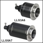
Thorlabs offers collimation adapters to couple Ø3 mm or Ø5 mm liquid light guides (LLGs) to our CSE2100 and CSE2200 Cerna Epi-Illuminator Modules; see the table at the bottom right for compatibility information. For even illumination at the back focal plane of the objective, these adapters feature an optic pair of an achromatic doublet and a double convex lens.
These adapters utilize a male D3T dovetail adapter to connect to the end of the epi-illuminator module; for additional information about microscope dovetails, see the full web presentation. The LLG is secured via a thumbscrew at the back of the adapter.
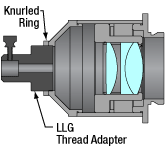
These adapters are calibrated such that the image plane from the LLG output is located at the back aperture of the objective when used with the compatible epi-illuminator module; to optimize illumination for your microscope or realign the image plane, the collimation can be fine-adjusted via the knurled ring on the thread adapter (see image to the bottom left).
| Specifications | ||||
|---|---|---|---|---|
| Item # | LLG3A6 | LLG5A6 | LLG3A7 | LLG5A7 |
| Effective Focal Length | 40 mm | 70 mm | ||
| Compatible Epi-Illuminator Module |
CSE2100 | CSE2200 | ||
| LLG Diameter | 3 mm | 5 mm | 3 mm | 5 mm |
| Collimating Optics | Achromatic Doublet & Double Convex Lens |
|||
| AR Coating | 350 nm - 650 nm Ravg < 0.5% at Each Surface |
|||
| Transmission Graph (Click Here for Raw Data) |
||||
| Numerical Aperture | 0.3 |
|||
| Magnification | Infinite | |||
Click to Enlarge
Cutaway View of LLG Collimation Adapter Depicting Multi-Element Design
Click for Details
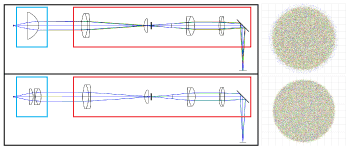
These simulations illustrate chromatic focal shift in a system with a collimated light source and a CSE2100 epi-illuminator module. A collimation adapter using a single optic (top) produces a larger focal shift for different wavelengths at the objective back aperture compared to a collimation adapter with a multi-element design (bottom).

Click to Enlarge
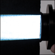
Output With Collimation Adapter
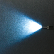
Click to Enlarge
Output Without Collimation Adapter

Click to Enlarge
Collimation Adapter Fitted to the Tip of an LLG
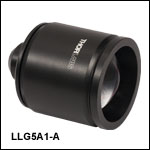
Thorlabs offers collimation adapters with AR-coated aspheric condenser lenses (EFL = 40 mm) for collimating the output from our light sources. Four different collimator housings are available; each is designed to mate to the illumination port on an Olympus IX/BX, Leica DMI, Zeiss Axioskop, or Nikon Eclipse Ti microscope.
These adapters quickly mount onto the end of either the Ø3 mm or Ø5 mm Liquid Light Guide (LLG). The LLG is secured into the back of the collimator via a 4-40 setscrew with a 0.050" hex.
| Optic Specifications | |
|---|---|
| Item # | ACL5040U-A Aspheric Condenser Lens |
| AR Coating | 350 nm - 700 nm, Ravg <0.5% at Each Surface |
| Focal Length | 40.00 mm ± 8% |
| NA | 0.60 |
| Magnification | Infinite |
| Surface Quality | 80-50 Scratch-Dig |
| Centration | <30 arcmin |


Click to Enlarge
As shown above, the LLG is correctly installed when the majority of the marking ring is within the LLG port.
- Yellow Band Visually Indicates when LLG is Fully Inserted Into the SLS603 or SLS605 Light Source
- High Transmission from 340 - 800 nm
- Homogenous Transmitted Beam and a Light Field Free of Dead Spots
- Flexible with Minimum Bend Radius of 40 mm (Ø3 mm Core) or 60 mm (Ø5 mm Core)
- Microscope Collimation Adapters Available Above
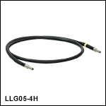
Thorlabs' Liquid Light Guides (LLGs) offer high transmission from 340 nm - 800 nm for white light illumination applications. These LLGs are offered from stock with a core diameter of either 3 or 5 mm, and in lengths of 4' (1.2 m), 6' (1.8 m), or 8' (2.4 m). For large core diameters, liquid light guides are a more efficient transmission solution than fiber bundles as they eliminate the packing fraction loss (dead space) in the light fields transmitted by optical fiber bundles. For more information about LLGs, please see the LLGs tab.
These Ø3 mm and Ø5 mm core LLGs are designed to be used with the SLS603 and SLS605 xenon arc light sources, respectively. Each light guide features a yellow band near one end, which indicates when the LLG is inserted to the correct depth in the LLG port of these light sources, as shown in the photo to the right.
Thorlabs also offers collimation adapters for our Ø3 mm and Ø5 mm liquid light guides, which are sold separately above. We also offer the AD3LLG and AD5LLG LLG to SM1 adapters for Ø3 mm Ø5 mm core LLGs, respectively.
 Products Home


 Zoom
Zoom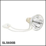


 LLG-Coupled Xenon Arc Light Sources