Clamping Forks for Ø1/2" Post Holders and Ø1" Pedestal Posts

- Base Adapters and Clamping Forks for Our Post Holders and Posts
- Flexible Positioning on an Optical Table or Breadboard
- Slots with Lengths from 0.40" to 2.12" (10.2 mm to 53.8 mm)
0.40" (10.2 mm)
Counterbored Slot
0.59" (14.9 mm) Counterbored Slot
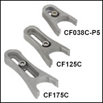
CF125C
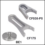
CF038-P5
Pack of 5
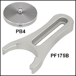
PF175B
1.30" (33.0 mm)
Clearance Slot
0.63" (15.9 mm) Clearance Slot
1.24" (31.5 mm)
Counterbored Slot
with Captive Screw
0.75" (19.1 mm)
Clearance Slot
2.12" (53.8 mm)
Counterbored
Slot
MSC2
MSC3
POLARIS-SCA1
POLARIS-CA1
Contact Pads
Maximize Overall
Clamp Stability
Post and
Base Not
Included
0.72" (18.3 mm)
Clearance Slot
SCF1

Please Wait
Click to Enlarge
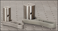
Our Ø1" and Ø1.5" posts can be secured to an optical table using post base adapters and clamping forks.
Features
- Clamping Forks Secure Pedestal-Style Mounts to the Optical Table or Breadboard
- Rigid One-Piece Construction with Relief Cuts to Maximize Clamping Stability
- Versions of Clamping Forks Available with Captive Screws
- Non-Bridging Clamping Arms with Flexure Clamping Mechanism
- Base Adapters Convert Posts and Post Holders to Pedestal-Style Mounts
Thorlabs offers clamping forks to secure our pedestal-style Ø1/2" post holders, Ø1" post holders, Ø1" pedestal posts, Ø12 mm pedestal posts, or Mini-Series post holders to breadboards and optical tables. With slots ranging from 0.40" to 2.12" (10.2 mm to 53.8 mm) in length, each fork can swivel around the pedestal-style post holder or post to access the most convenient mounting holes on the optical table or breadboard. Thorlabs also manufactures Non-Bridging Clamping Arms for Ø1" or Ø25 mm posts, which provide high holding force with minimal torque.
Our base adapters feature either threaded mounting holes (for use with a setscrew) or studs that thread directly onto our Ø1/2" post holders, Ø1" post extensions, or Ø1.5" posts to convert them into pedestal-style posts. The clamping forks can then be used to hold the posts or post holders in place by clamping over the base adapter.
Please note that significant overtightening of clamping forks can deform the surface of an optical table, which can cause misalignment of components. This effect is minimized with the use of Non-Bridging Clamping Arms; see below for details.
An alternative method for securing Ø1" and Ø1.5" pedestal posts is a pair of CL8 table clamps. These compact pieces are part of our larger selection of table clamps and allow users to secure posts to breadboards and tables with limited space.
Insights into Best Lab Practices
Scroll down to read about a few things we consider when setting up lab equipment.
- Clamping Forks: Tip for Maximizing the Holding Force
- Optical Tables: Clamping Forks and Distortion of the Table's Surface
Click here for more insights into lab practices we follow.
Clamping Forks: Tip for Maximizing the Holding Force
Click to Enlarge
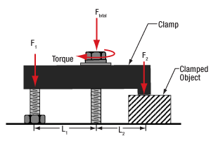
Figure 2: More than half the total applied force (FTotal) holds the object, since L1 > L2. The height of the left leg of this CL2 clamp is variable to compensate for the object's height. This allows the clamp's top surface and the mounting surface to be made parallel.**
Click to Enlarge
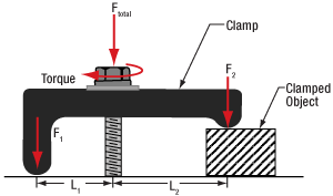
Figure 1: Less than half the total applied force (FTotal) holds the object, since L1 < L2. The clamp illustrated above is the CL5A.
Clamped objects can be fairly easy to move when the torqued screw in the clamp's slot is positioned too far from the object. Correct positioning of the screw protects clamped objects from being knocked out of position.
To maximize the clamping force, position the screw as close as possible to the object.**
This works since clamps like CL5A and CL2 (Figures 1 and 2, respectively) divide the torqued screw's applied force (FTotal) between two points.
Clamping force F2 is applied to the object. The value of F2 is a percentage of FTotal and depends on L1 and L2, as described below. The remainder (F1) of the total force is applied through the opposite end of the clamp.
The following equations can be used to calculate the two applied forces.
Object: |
 |
|
| Force Applied to Other Contact Point: |
 |
These equations show that the clamping force on the object increases as the distance between the object and screw decreases. The force supplied by the torqued screw is evenly divided between F1 and F2 when L1 and L2 are equal.
**Note that maximizing the clamping force also requires both the top surface of the clamp and the area it contacts on the object to be parallel with the mounting surface, as depicted in Figures 1 and 2.
If the tangent at the interface between the clamp and object is not parallel to the mounting surface, the force applied to the object will be divided between pressing it into and pushing it across the mounting surface. The force directed along the mounting surface may, or may not, be sufficient to translate the object.
To accommodate different object heights, clamps like the CL2 have one threaded, variable-length leg, which is shown on the left in Figure 2. The number of threads between the clamp and mounting surface should be adjusted to compensate for the height of the object and to keep the clamp's top surface level with the table.
Date of Last Edit: Dec. 4, 2019
Optical Tables: Clamping Forks and Distortion of the Table's Surface
Click to Enlarge
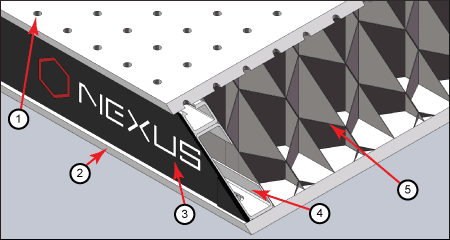
Figure 3: The construction of a Nexus table / breadboard includes a (1) top skin, (2) bottom skin, (3) side finishing trim, (4) side panels, and (5) honeycomb core. The stainless steel top and bottom skins are 5 mm thick.
Clamping forks are more rigid than the mounting surface of composite optical tables. It might be expected that the spine of the clamping fork would bend with the force exerted by the screw as the torque is increased. Instead, the screw will pull the skin of the table up and out of flat before the clamping fork deforms. Due to this, clamping forks should be used with care when securing components to optical tables. Clamping arms, which are discussed in the following, are alternatives to clamping forks that are less likely to deform the table's mounting surface.
Optical Table Construction
Optical tables and breadboards with composite construction (Figure 3) are designed to be rigid while providing vibration damping. The 5 mm thick, stainless steel top skin is manufactured to be flat, but a localized force can deform it. When the top skin is deformed, optical components will not sit flat, and optical system alignment and performance can be negatively affected.
Clamping Forks
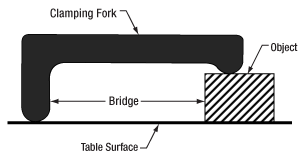
Standard clamping forks are installed with one edge placed on the table's surface and the opposite edge on the object (Figure 4). Between these two edges, there is clearance between the bottom of the clamp and the surface of the table. This bridge makes it possible to use a single screw to both secure the clamp to the table and exert a holding force on the object.
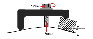
When the clamp is secured by torqueing the screw, the screw pulls up on the top skin of the table (Figure 5).
As the torque on the screw increases, the top skin of the table rises. Not only does pulling up on the table surface risk permanently damaging the table, this can also disturb the alignment of the optical component the clamp is being used to secure. By lifting the table's skin, the mounting surface under the clamped object tilts.
Click to Enlarge
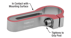
Figure 6: The POLARIS-CA1/M clamping arm has a slot that accepts a mounting screw, a separate screw that applies a clamping force to an installed post, and identical top and bottom surfaces. Since a nearly continuous track around the surface of the clamping arm is in contact with the mounting surface, clamping arms cause negligible bridging effects.
Click to Enlarge
Figure 5: Torqueing the screw creates a force that pulls up on the table's top skin. The lifted skin tilts the mounting surface and can induce angular deviation of the object. This effect is exaggerated in the above image for illustrative purposes.
Click to Enlarge
Figure 4: A standard clamping fork, such as the CL5A, contacts the table along only one edge. The opposite edge is in contact with the object to be secured. A bridge forms between the two. The screw that applies the clamping force is not shown.
Clamping Arms
Clamping arms, such as the POLARIS-CA1/M, shown in Figure 6, are designed to secure a post while minimally deforming the mounting surface.
The clamping arm in Figure 6 differs from clamping forks in two significant ways. One is the surface area that makes contact with the optical table, which is highlighted in red, and the other is the method used to secure the post.
The area in contact with the optical table makes a nearly continuous loop around the base of the clamp. The contact area is flat and flush with the table when the clamp is installed. The only break in the loop is a narrow slot in the vise used to grip the post.
This design uses two screws, instead of the clamping fork's single screw. One screw (not shown) secures the clamp to the table, and the other (indicated) is tightened to grip the post. Since one screw is not required to perform both tasks, it is not necessary for this clamping arm to form a bridge between the clamped object and the optical table.
Although the contact area is a loop, and not a solid surface, this clamp causes negligible distortion of the mounting surface. This is due to the open area inside the contact surface being narrow and surrounded by the sides of the clamp, which resist the force pulling up on the table.
Date of Last Edit: Dec. 4, 2019
| Posted Comments: | |
Randall Moss
(posted 2023-11-08 07:58:35.367) Can you update the UNSPC to 31162900 ? jdelia
(posted 2023-11-10 10:55:45.0) Thank you for contacting Thorlabs. I have reached out to you directly to discuss this further. user
(posted 2023-11-02 09:03:55.837) will be nice to see retainer and screw as separate products cdolbashian
(posted 2023-11-02 12:42:45.0) Thank you for reaching out to us with this feedback! While we do not have them on the website for purchase, we are happy to assist you in locating a vendor for replacement retainers! I would recommend contacting your local tech support office. A list of our local offices can be found here on our contacts page: https://www.thorlabs.com/locations.cfm user
(posted 2022-04-20 13:54:27.86) in many situations, the same article with a M4 thread would be really useful. Does this product already exist ?
thank you very much in advance,
best regards jdelia
(posted 2022-04-27 08:28:07.0) Thank you for contacting Thorlabs. We unfortunately do not offer any version of the PB4(/M) with an M4 stud instead of M6. However, you could use an internal M6 - external M4 screw thread adapter like AS6M4M. I have reached out to you directly to discuss your application requirements. John West
(posted 2020-12-18 18:41:25.717) PB4 - Studded Pedestal Base Adapter, 1/4"-20 Thread
Do you have is as a magnet ? llamb
(posted 2020-12-23 10:51:24.0) Thank you for your feedback. We do not currently have a magnetic version of the PB4 pedestal base adapter. I have added your idea into our internal product forum for further consideration. Eleicer Ching Prado
(posted 2020-11-22 14:14:01.89) I need:
1- CF 125C (one): 1/2" optical post.
2- PH082E (one): 1/2 Pedestal post Holder.
3- In this third optical part, I need help: It must be like a TR1 (optical post) with 1/4"-20 set screw (No a 8-32 Set screw). It is for support an optical fiber holder (spectrometer detector) with a 1/4"-20 female. (one).
The deliver address must be:
Eleicer Ching
1 Aeropost Way, PTY-86271
Miami, FL 33206-3206
United States
Phone: +1 305-592-7754
The customer address ( to bill) must be:
Eleicer Ching
Technological University of Panama
Víctor Levi Sasso Campus
Panama city, Panama
Thanks..........Eleicer YLohia
(posted 2020-11-23 02:33:15.0) Thank you for contacting Thorlabs. We offer the RS1P, which is a 1" diameter pedestal post with 1/4"-20 threads on both ends. If you would rather use a 1/2" diameter post, you may use the AP8E25E screw thread adapter with the TR1 post. Quotes for stock items can be requested by emailing sales@thorlabs.com. We will contact you directly. user
(posted 2020-06-02 16:31:12.933) Could you please specify the adhesion force of this magnetic base or it's magnet (BE1R/M)?
Best regards, Andreas YLohia
(posted 2020-06-03 02:14:42.0) Hello Andreas, thank you for contacting Thorlabs. The calculated pull force for the magnet in the BE1R[/M] is 13.33 lbf. The tested slide force for the BE1R[/M] is 2 lbf. Nicholas Breslin
(posted 2019-10-28 11:21:50.487) Is there any consideration to make a CF model between the CF038 and the CF125. For compact optical setups using a CF038 is preferable, but sometimes the range just isn't enough to find a good screw hole but the CF125 has too large of a footprint and starts to remove the ability to be compact. It would be nice to have some options between 038 and 125. Like a 075 or a 100 even llamb
(posted 2019-10-28 05:20:47.0) Hello Nicholas, thank you for your feedback. I have added this idea for a more mid-sized clamping fork to our internal product forum for further review. avnerf
(posted 2017-05-07 00:50:26.64) Dear Sir/Madam
Is the CF175 clamping fork made of a solid bar of 303 stainless steel (CNC processed) or from sintered stell powder ( as it used to be for the last 10 years or so)?
Thanks nbayconich
(posted 2017-05-18 12:35:48.0) Thank you for contacting Thorlabs. The CF175 clamping fork is made from sintered 303 stainless steel. A techsupport representative will contact you directly. user
(posted 2017-02-24 17:38:35.58) new large quantity pack for BE1 bases:
BE1-P5 jlow
(posted 2017-03-01 04:55:34.0) Response from Jeremy at Thorlabs: Thank you very much for the suggestion. We will look into carrying this. chenav
(posted 2016-11-16 14:42:23.88) I am sorry to say the design of the captive-screw clamps is really terrible. The idea is great, but in practice when the screw is turned the whole clamps slides back and forth as a result. It's funny at first, but very soon you realize you need three hands to use these clamps: one to hold a screwdriver, another to hold the optic being clamped, and a THIRD to hold the clamp from sliding away from the post base. Unfortunately, most people in our lab indeed do not have three hands available. Sadly we've ordered a large quantity of these clamps without testing them first, and had to give them all to a graduate student so they can remove the captive screw. We now use them as standard clamps and all is well. tmorgus
(posted 2016-11-16 10:01:22.0) Hello Chenav, It is true that one disadvantage to the captive screw is that the clamping fork will move if not restrained as the screw is tightened. My technique for using the captive screw clamping forks is to use two fingers on the hand holding the post to pull the clamping fork into the post as I am tightening the screw with the other hand. I tend to do this even for the non captive screw version because I feel that without the restraining force on the clamp a small shift is possible just as the clamping screw gets tight. I will contact you directly as I would like to make the situation right for you. Tyler, Mechanics Business Unit Leader piksarv
(posted 2014-11-27 17:06:24.95) It would be nice if the hex socket on the bottom of PB4/M for tightening the pedestal base adapter to a post would be also metric. cdaly
(posted 2014-12-02 04:00:48.0) Response from Chris at Thorlabs: According to our internal machine drawings, which the PB4/M is produced from, the hex socket on the bottom accepts a 3mm hex. The drawing online is mislabeled and I will have this updated as soon as possible. Jurgen.Stampa
(posted 2014-07-25 17:26:59.97) I had to laugh. These captive screw forks have been around for a long while - like I used them in grad school 15 years ago. Is it customer-inspired innovation or some one just recycling an old design? cdaly
(posted 2014-08-06 06:23:34.0) Response from Chris at Thorlabs: Customer inspired indicated it was requested by our customers and as a result of their input we now offer it as a product in our catalog. cbrideau
(posted 2014-05-09 13:17:44.31) I am constantly struggling with aligning the screws in the 'classic' forks. The new captive screw forks look much better. Great innovation! cdaly
(posted 2014-05-22 10:28:59.0) Response from Chris at Thorlabs: Thank you for your feedback. We're glad to hear you like the newer version. |

Click to Enlarge
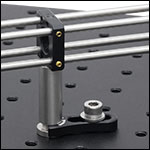
An MSC2 Clamping Fork secures a Mini-Series pedestal post to a breadboard with 1/4"-20 tapped holes.
- Secure Any of Our Ø12 mm Pedestal Posts or Pedestal-Base Post Holders to Breadboards or Optical Tables
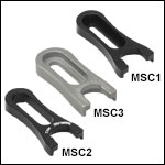
- MSC1 Has a 0.63" (15.9 mm) Long Counterbored Slot for a 4-40 (M3) Cap Screw
- MSC3 Has a 0.59" (14.9 mm) Long Counterbored Slot for an 8-32 (M4) Cap Screw
- MSC2 Has a 0.63" (15.9 mm) Long Slot for a 1/4"-20 (M6) Cap Screw
- Swivel Fork 360° to Select the Most Convenient Mounting Hole
Our clamping forks are designed to provide exceptional clamping force when used with our Ø12 mm pedestal posts or our pedestal-base post holders. These clamping forks provide flexibility for building setups that combine Mini-Series components and our larger range of optomechanics offerings. The MSC1 and MSC2 are made from anodized aluminum, while the MSC3 is made from precipitation hardened 17-4PH stainless steel to provide a more uniform clamping force.
Designed to be used with the Mini-Series breadboards, the MSC1 and MSC3 are compatible with a 4-40 (M3) and 8-32 (M4) cap screw, respectively. The MSC2 slot accepts 1/4"-20 (M6) cap screws, thus enabling the inclusion of Mini-Series posts and components into setups on standard breadboards and optical tables in addition to mini-series breadboards.
Each clamping fork features landing pads on the bottom surface to maximize stability when using a washer and cap screw to lock down a post with the fork. Please note that significant overtightening of clamping forks can deform the surface of an optical table, which can cause misalignment of components.

Click to Enlarge
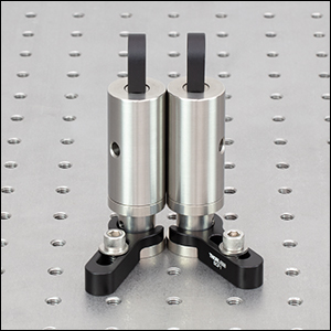
Two SCF1 clamping forks hold two SBE2 adapters supporting a pair of lenses to form a compact beam expander.
Click to Enlarge
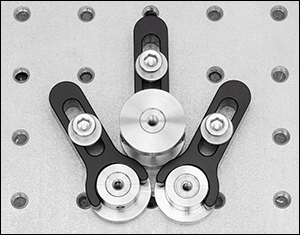
Three SCF1 clamping forks hold three space-saving pedestal base adapters in close contact, providing a platform for mounting posts with only 1" center-to-center separation.
- SBE1(/M) and SBE2(/M) Adapters Convert Ø1/2" Post Holders and Ø1" Posts to Pedestal-Style Mounts
- SBE1(/M): 8-32 (M4 x 0.7) Threads
- SBE2(/M): 8-32 (M4 x 0.7) and 1/4"-20 (M6 x 1.0) Threads
- Space-Saving Ø1" (Ø25.0 mm) Bases and Narrow Clamping Fork Design Allow Mounting Optomechanical Components in Compact Setups
- Compact Clamping Fork Secures Space-Saving Pedestal Base Adapters to a Breadboard or Optical Table
- 0.98" (24.9 mm) Across at Widest Point
- 0.72" (18.3 mm) Long Clearance Slot for Mounting via 1/4" (M6) Cap Screws
- Swivel Fork 360° to Select Most Convenient Mounting Hole
Click to Enlarge
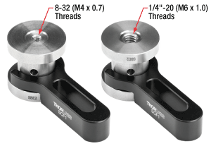
The SBE2(/M) adapter can be flipped to utilize either the 8-32 (M4 x 0.7) mounting threads (left) or the 1/4"-20 (M6 x 1.0) mounting threads (right), as shown here.
Pedestal Base Adapters
The SBE1(/M) and SBE2(/M) Ø1" (25.0 mm) Pedestal Base Adapters are machined from non-magnetic 303 stainless steel and offer a low-profile option for mounting our Ø1" pillar posts, fixed lens mounts, Ø1/2" post holders, and any other optomechanical components that are compatible with either 8-32 (M4 x 0.7) or 1/4"-20 (M6 x 1.0) threads. They feature a Ø1" (25.0 mm) base that does not extend beyond the diameter of our Ø1" pillar posts and are designed to be held securely to a breadboard by our SCF1 Compact Clamping Fork, making them ideal for applications where table space is limited (see photo to the right).
The SBE1(/M) pedestal base adapter is 1/2" (12.5 mm) long and features an 8-32 (M4 x 0.7) tapped thru hole for directly mounting an 8-32 (M4 x 0.7)-threaded Ø1" pillar post via an 8-32 (M4 x 0.7) setscrew (such as Item # SS8S050 (SS4MS12)). The SBE2(/M) double pedestal base adapter is 1" (25.0 mm) long and features 8-32 (M4 x 0.7) internal threads with a depth of 0.30" (7.6 mm) on one end and 1/4"-20 (M6 x 1.0) internal threads with a depth of 0.38" (10.2 mm) on the other. With a pedestal base on both ends, the double pedestal base adapters can be flipped upside-down depending on which thread size is needed, as shown in the photo to the left. In addition to the 8-32 (M4 x 0.7) mounting options mentioned above, the added versatility of the 1/4"-20 (M6 x 1.0) threads enables direct mounting to 1/4"-20 (M6 x 1.0)-threaded Ø1" pillar posts or our standard Ø1/2" post holders via a 1/4"-20 (M6 x 1.0) setscrew (such as Item # SS25S050 (SS6MS12)).
Each of these pedestal base adapters also has a recessed Ø0.65" (Ø16.5 mm) central pillar above the 0.20" (5.1 mm) thick base, providing a clamping surface for our SCF1 compact clamping fork. All space-saving pedestal base adapters can also be mounted directly to a breadboard or optical table using the aforementioned setscrews.
Clamping Fork
The SCF1 compact clamping fork is designed to securely attach our space-saving pedestal base adapters to an optical table or breadboard. Its low-profile design, compatible only with the SBE1(/M) and SBE2(/M) pedestal base adapters, is ideal for compact optical setups. Instead of clamping down on the top and sides of the bases, these forks hug the recessed center pillar and only make contact with top of the base, making the diameter of the base the limiting factor for spacing. Thus, these clamping forks can hold two posts with their centers only 1" apart, as shown in the photos to the right, compared with the minimum 1.43" separation achieved with two adjacent CF125 clamping forks, or 1.25" for opposing clamp positions where the BE1 bases are touching. Made from anodized aluminum, the SCF1 clamping fork creates three points of contact with the table for high stability. The 0.72" (18.3 mm) long clearance slot for 1/4" (M6) cap screws (such as Item # SH25S075 (SH6MS20)) allows the most convenient mounting hole to be selected. Please note that significant overtightening of clamping forks can deform the surface of an optical table, which can cause misalignment of components and decrease stability.

Click to Enlarge
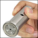
The BE1R has a magnet in the base for stability in temporary setups.
 Click to Enlarge
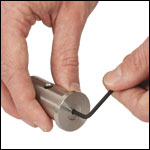
These base adapters feature a 1/8" (3 mm) hex socket on the bottom for tightening.
 Click to Enlarge
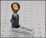
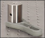
A CF125 fork is used to secure a Ø1/2" post holder to an optical table with a BE1 base.
Click to Enlarge
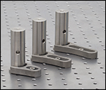
Several Slot Lengths Available
- BE1(/M) and BE1R(/M) Adapters Convert Standard Ø1/2" Post Holders and Ø1" Post Extensions into Pedestal-Style Mounts
- Clamping Fork or CL8 Table Clamp Secures Pedestal-Style Mount to a Breadboard or Optical Table
- Three Sizes Provide Clamping with 1/4"-20 (M6) Cap Screws
- 0.40" (10.2 mm) Long Counterbored Slot (CF038-P5)
- 1.24" (31.5 mm) Long Counterbored Slot (CF125)
- 1.75" (44.4 mm) Long Counterbored Slot (CF175)
- Swivel Fork 360° to Select Most Convenient Mounting Hole
- BE1(/M) Adapter and All Clamping Forks Available in Packs of Five (CF038-P5 Not Sold Individually)
Pedestal Base Adapters
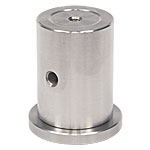
The BE1(/M) and BE1R(/M) pedestal base adapters feature 1/4"-20 (M6)-threaded studs that fit into the bottom of our standard Ø1/2" post holders or Ø1" post extensions (see photos to the right), converting them into pedestal-style mounts for added stability. The BE1R(/M) adapter has a magnet in the base that is sufficiently strong to securely hold the base in place without clamping to an optical table (see photo at the top right). Made from solid 303 stainless steel with a 1.25" (31.8 mm) outer diameter, these adapters allow Ø1/2" post holders and Ø1" pillar posts to be used with the CF series of clamping forks, and can be tightened onto the post or postholder using a 1/8" (3 mm) hex or ball driver.
The BE1(/M) base adapter is available in a pack of five for ease of ordering.
Clamping Forks
The CF038-P5, CF125, and CF175 clamping forks are designed to provide exceptional clamping force when used with our Ø1/2" post holders and Ø1" post extensions that have been adapted using the BE1(/M) to pedestal-style mounts. These clamping forks can also be used with our pedestal-style Ø1/2" post holders or Ø1" pedestal posts without any need for the BE1(/M).
Made from solid 303 stainless steel, the CF038-P5, CF125, and CF175 clamping forks create three points of contact with the table for high stability. For flexibility in the positioning of post assemblies, three sizes are available: the CF038-P5 fork offers a 0.40" (10.2 mm) long counterbored slot, the CF125 fork offers a 1.24" (31.5 mm) long counterbored slot, and the CF175 fork has a 1.75" (44.4 mm) long counterbored slot. All three counterbored slots are designed for 1/4"-20 (M6)-threaded cap screws. Please note that significant over tightening of clamping forks can deform the surface of an optical table, which can cause misalignment of components and decrease stability.
These clamping forks are available with a 1/4"-20 (M6)-threaded captive screw. For more information, please see below. Clamping forks are also available in packs of five for ease of ordering (note: the CF038-P5 clamping fork is only available in packs of five).

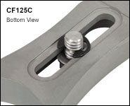
Click for Details
Bottom view of the captive screw held in the slot by a retainer.
- Hold BE1(/M) and BE1R(/M) Adapters to Convert Standard Ø1/2" Post Holders and Ø1" Post Extensions into Pedestal-Style Mounts
- Same Design as CF038, CF125 or CF175 with Added 1/4"-20 (M6) Captive Screw
- Secures Pedestal-Style Mount to a Breadboard or Optical Table
- Three Sizes Provide Clamping with 1/4"-20 (M6) Cap Screws
- 0.40" (10.2 mm) Long Counterbored Slot [CF038C(/M)-P5]
- 1.24" (31.5 mm) Long Counterbored Slot [CF125C(/M)]
- 1.75" (44.4 mm) Long Counterbored Slot [CF175C(/M)]
- Position Fork Over 360° to Select Most Convenient Mounting Hole
- Clamping Forks Available in Packs of Five [CF038C(/M)-P5 Not Sold Individually]
Our Clamping Forks offer the convenience of 1/4"-20 (M6) captive screws, while still providing the same exceptional clamping force for our pedestal-style posts and post holders as our standard forks, sold above. The screws can be tightened into the breadboard using a 3/16" (5 mm) hex key or balldriver. Please note that significant over tightening of clamping forks can deform the surface of an optical table, which can cause misalignment of components.
Fabricated from solid 303 stainless steel, all of these clamping forks create three points of contact with the table for high stability. For flexibility in the positioning of post assemblies, Thorlabs offers three sizes: the CF038C(/M)-P5 fork has a 0.40" (10.2 mm) long counterbored slot, the CF125C(/M) fork has a 1.24" (31.5 mm) long counterbored slot, and the CF175C(/M) fork has a 1.75" (44.4 mm) long counterbored slot. When used with the BE1(/M) base adapter (sold above), these clamping forks can position our standard Ø1/2" post holders or Ø1" post extensions. Alternatively, the clamping fork is directly compatible with our pedestal-style Ø1/2" post holders or Ø1" pedestal posts.
These clamping forks are also available in packs of five for ease of ordering (note: the CF038C(/M)-P5 clamping fork is only available in packs of five).

Click to Enlarge
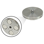
The PB4R(/M) has a 3/16" (5 mm) hex socket and four magnets in the base.
- PB4(/M) and PB4R(/M) Ø1.85" (Ø47.0 mm) Adapters Convert Ø1" Post Holders and Ø1.5" Posts to Pedestal-Style Mounts
- Clamping Forks Secure Pedestal-Style Mount to a Breadboard or Optical Table
- 2.11" (53.5 mm) Outer Diameter
- Three Counterbored Slot Options:
- 0.85" (21.6 mm), 1.25" (31.8 mm), or 2.12" (53.8 mm)
- Swivel Fork 360° to Select Most Convenient Mounting Hole
- Available Individually or in Packs of 5
Pedestal Base Adapters
The PB4(/M) and PB4R(/M) pedestal base adapters feature a 1/4"-20 (M6)-threaded stud, which fits into the bottom of our Ø1.5" posts to convert them into pedestal-style mounts. Made from solid 303 stainless steel with a 1.85" (47.0 mm) outer diameter, these adapters allow these posts to be used with our clamping forks. The PB4(/M) can be tightened onto the post or postholder using a 1/8" (3 mm) hex key or ball driver, while the PB4R(/M) has a 3/16" (5 mm) hex socket as well as four high strength magnets in the base that are sufficiently strong to securely hold the base in place without clamping to an optical table.
Clamping Forks
The PF85B, PF125B, and PF175B clamping forks are designed to provide exceptional clamping force when used with our Ø1.5" posts that have been adapted using the PB4(/M) or PB4R(/M) pedestal bases. These clamping forks can also be used with our Ø1" post holders or BLP01 adjustable-height post without any need for the PB4(/M) or PB4R(/M) bases.
Made from stainless steel, these clamping forks create three points of contact with the table for high stability. The counterbored slots for 1/4"-20 (M6) cap screws allow the most convenient mounting hole to be selected. For flexibility in the positioning of post assemblies, Thorlabs offers three sizes: the PF85B fork has a 0.85" (21.6 mm) long counterbored slot, the PF125B fork has a 1.25" (31.8 mm) long counterbored slot, and the PF175B fork has a 2.12" (53.8 mm) long counterbored slot. Please note that significant overtightening of clamping forks can deform the surface of an optical table, which can cause misalignment of components and decrease stability.
These clamping forks are available individually or in packs of five.

Click to Enlarge
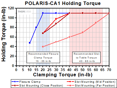
Click for POLARIS-CA1/M Holding Torque Results*
The non-bridging clamping fork design has undergone extensive testing to ensure high-quality performance. See the full presentation for more details.
*It is important to note that the 1/4"-20 and M6 x 1.0 clamping torque values have been adjusted to provide the same clamping post and table forces. Also note that the maximum recommended tightening torque for an 18-8 stainless steel screw is 75.2 in-lbs for a 1/4"-20 screw and 8.8 N-m for an M6 x 1.0 screw. Higher mounting torques can cause the screw to fail.
Click to Enlarge
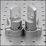
The arm can be mounted with either flat surface in contact with the table, allowing for compact setups.
Click to Enlarge
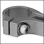
Side-Located 1/4"-20 (M6) Screw Actuates Clamping Bore
- 3-Point Contact Bore with Flexure Clamping Mechanism
- Versions for Ø1" or Ø25 mm Posts for Polaris Mounts and Ø1" Monolithic Polaris Mount (See Table Below)
- 0.60" Bore Depth Supports Height Adjustments Up to 0.25"
- Allows Posts to be Rotated 360°
- 0.75" (19.1 mm) or 1.30" (33.0 mm) Slot for 1/4"-20 (M6) Cap Screw
- Heat-Treated, Stress-Relieved Stainless Steel Provides Large Clamping Force
- Design Supports Left- and Right-Handed Orientations (See Lower Left Image)
- High Stability Ideal for Use with Our Kinematic Polaris Mirror Mounts
- Vacuum Compatible to 10-9 Torr at 25 °C with Proper Bake Out
- ±0.001" (±0.02 mm) Surface Flatness
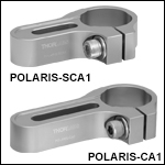
Thorlabs' Non-Bridging Clamping Arms are the ideal solution for stably mounting our Ø1" or Ø25 mm Posts for Polaris Mounts or Ø1" Monolithic Polaris Mount. Each clamping arm, which is machined from heat-treated, stress-relieved stainless steel bar stock, provides extremely high holding forces with minimal torquing of the mounting screws (see the graph to the right).
The flat, non-bridging top and bottom surfaces of each clamping arm allow it to be used with either side in contact with an optical table or other mounting surface. This feature allows the clamp to be positioned in left- or right-handed orientations and optical components to be placed in near contact to one another while minimizing the footprint (see the image to the left). On each side of the arm, a relief cut around the slot protects the ±0.001" (±0.02 mm) flat surface from any marring due to the screw and washer, allowing for more stable mounting.
The clamping arms are offered with slot lengths of 0.75" (19.1 mm) or 1.30" (33.0 mm), providing flexibility when used in applications such as tight laser cavity setups. Four of our clamping arms are designed to hold Ø1" posts, while the remaining two are designed to hold Ø25 mm posts; see the table below for details. Note the arms with a Ø1" (25.4 mm) bore are not compatible with Ø25 mm posts; the bore diameter is too large and will not contact the post when clamping.
Non-Bridging Design: Industry Standard Clamping Fork
vs. Thorlabs' Non-Bridging Clamping Arm
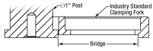
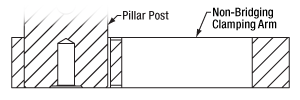
Industry standard clamping forks are designed with a bridge, as shown in Figure 1, for clamping to pedestal-style posts or post holders. This design will slightly damage the laser platform during each use by pulling up the part of the platform located under the bridge. The Thorlabs clamping arm, as shown in Figure 2, is designed with a flat top and bottom to eliminate this problem.
 Click to Enlarge
Figure 1: A Bridge is Created When an Industry Standard Clamping Fork is Used with a Pedestal Post
 Click to Enlarge
Figure 2: The Thorlabs Clamping Arm Eliminates the Bridge Created by an Industry Standard Clamping Fork
The flexure clamp, shown in the photo to the left, is actuated using a side-located 1/4"-20 (M6 x 1.0) cap screw and allows a post to be rotated 360° about its center. As the flexure clamp and mounting slot are secured with separate screws, the position of the fork and the rotational alignment of the post can be adjusted independently. While best performance is achieved with full post engagement, the 0.60" (15.2 mm) thick mounting bore supports up to 0.25" of post height adjustment.
The non-bridging clamping arm design has undergone extensive testing to ensure high-quality performance; see the graph to the upper right. For optimal performance, we recommend tightening the flexure clamping screw of an imperial clamping arm with 15 to 25 in-lb of torque and the flexure clamping screw of a metric clamping arm with 1.75 to 3 N•m of torque. When mounting to a table or platform, we recommend using 40 to 65 in-lb of torque for an imperial clamping arm and 4.75 to 7 N•m of torque for a metric clamping arm. Please note that the values for imperial and metric clamps are not a direct conversion due to an efficiency difference between 1/4"-20 and M6 x 1.0 screws. The efficiency of M6 x 1.0 screws is about 5% less than that of 1/4"-20 screws due to differences in diameter and pitch. For best results, use the maximum recommended torques from each range. These torque values can be dialed in using a torque driver.
| Item # | Compatible Post Size |
Clamping Screw |
Slot Length | Footprint |
|---|---|---|---|---|
| POLARIS-SCA1 | Ø1" (25.4 mm) |
1/4"-20 (3/16" Hex) |
0.75" (19.1 mm) |
2.78" x 1.60" (70.5 mm x 40.6 mm) |
| POLARIS-CA1 | 1.30" (33.0 mm) |
3.33" x 1.60" (84.5 mm x 40.6 mm) |
||
| POLARIS-SCA1/M | M6 x 1.0 (5 mm Hex) |
0.75" (19.1 mm) |
2.78" x 1.60" (70.5 mm x 40.6 mm) |
|
| POLARIS-CA1/M | 1.30" (33.0 mm) |
3.33" x 1.60" (84.5 mm x 40.6 mm) |
||
| POLARIS-SCA25/M | Ø25.0 mm (Ø0.98") |
0.75" (19.1 mm) |
2.78" x 1.60" (70.5 mm x 40.6 mm) |
|
| POLARIS-CA25/M | 1.30" (33.0 mm) |
3.33" x 1.60" (84.5 mm x 40.6 mm) |
 Products Home


 Zoom
Zoom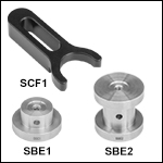
 Clamping Forks