 Products Home
Manual Rotation Stages
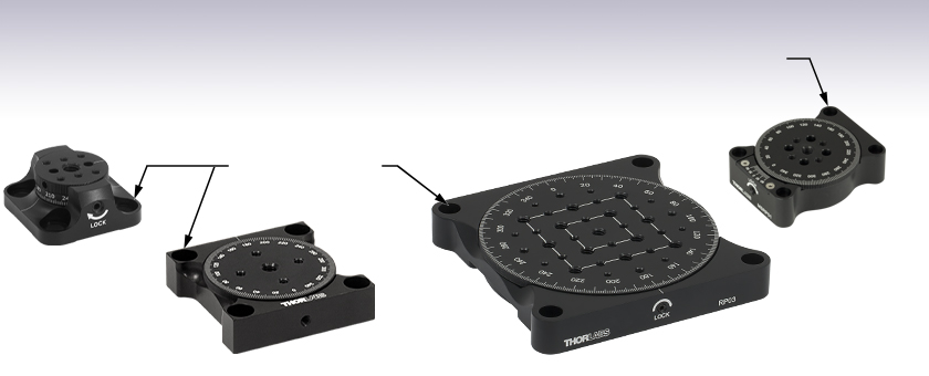
- Continuous 360° Rotation
- Ø1", Ø1.4", Ø2", or Ø4.3" Rotating Platform
- Backlash-Free, Low-Profile Design
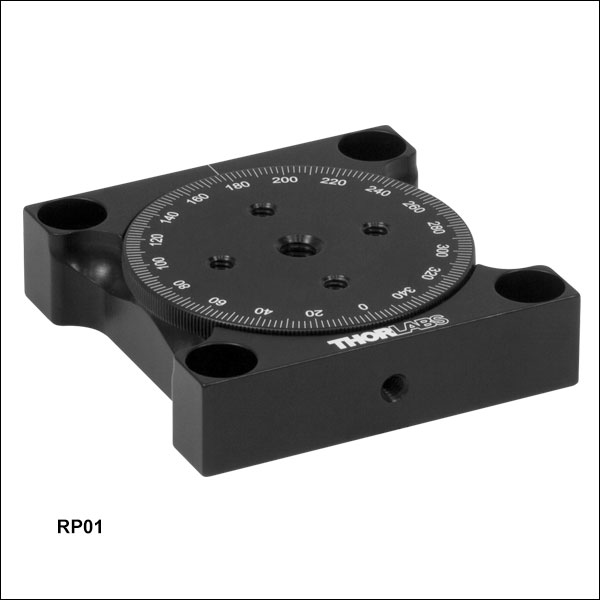
RP01
Ø2" Manual
Rotation Stage
MSRP01
Ø1.4" Manual
Rotation Stage
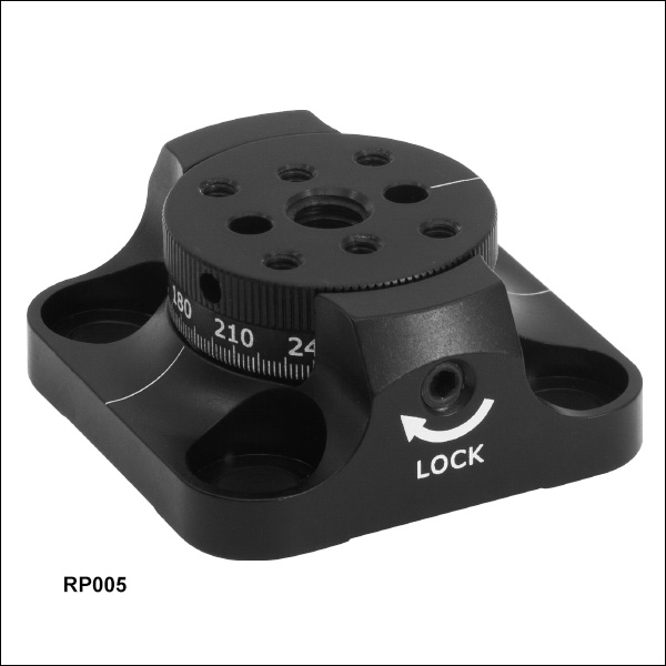
RP005
Ø1" Manual
Rotation Stage
1/4" (M6) Counterbores for Mounting to an Optical Table or Breadboard
#4 (M3) Counterbores for Mounting to a Mini-Series Breadboard
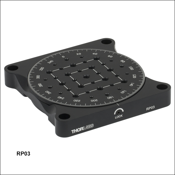
RP03
Ø4.3" Manual
Rotation Stage


Please Wait
| Rotation Stage Comparison | ||||
|---|---|---|---|---|
| Item # | RP005(/M) | MSRP01(/M) | RP01(/M) | RP03(/M) |
| Rotating Platform Size |
Ø1.00" (25.4 mm) | Ø1.40" (35.6 mm) | Ø2.07" (52.8 mm) | Ø4.29" (109.0 mm) |
| Component Mounting Taps |
Six 4-40 (M3) One 1/4"-20 (M6) |
Four 4-40 (M3) One 8-32 (M4) |
Four 8-32 (M4) One 1/4"-20 (M6) |
Eight 6-32 (M4) Sixteen 8-32 (M4) Thirteen 1/4"-20 (M6) |
| Side Tap for Post Mounting |
No | Yes; 4-40 (M3) | Yes; 8-32 (M4) | Yes; 8-32 (M4) |
| Stage Height | 0.67" (17.0 mm) | 0.51" (13.1 mm) | 0.63" (16.1 mm) | 0.70" (17.8 mm) |
| Stage Dimensions | 1.50" x 1.50" (38.1 x 38.1 mm) |
1.78" x 1.40" (45.2 x 35.6 mm) |
2.45" x 2.45" (62.2 x 62.2 mm) |
4.65" x 4.65" (118.1 x 118.1 mm) |
Features
- Continuous 360° Rotation
- Laser-Engraved Graduation Marks
- Ø1", Ø1.4", Ø2", or Ø4.3" Mounting Platform
- 1/4" (M6) or #4 (M3) Counterbores for Breadboard Mounting
- Lockable via Side-Located Setscrew
Thorlabs' Manual Rotation Stages are cost effective platforms for an optomechanical component requiring smooth, backlash-free rotation. Each stage offers 360º of continuous rotation with a Ø1", Ø1.4", Ø2", or Ø4.3" mounting platform and utilizes needle roller thrust bearings for higher load capacities. An engraved angular scale along the edge of each stage's rotating platform allows the user to set the angular orientation of the stage. Rotation of the platform can be locked by tightening the side-located setscrew. Four corner-located counterbored holes are spaced for direct fastening to an optical table or breadboard.
Tholabs also offers a selection of other manual stages that are micrometer driven, have central through holes, or have built-in hard stops. For our entire selection of rotation stages, please see the Rotation Mounts and Stages tab.
Reading a Vernier Scale on a Linear Main Scale
Vernier scales are typically used to add precision to standard, evenly divided scales (such as the scales on Thorlabs' rotation, goniometric, or translation mounts). A vernier scale has found common use in many precision measurement instruments, the most common being calipers and micrometers. The vernier scale uses two scales side-by-side: the main scale and the vernier scale. The direct vernier scale has a slightly smaller spacing between its tick marks owing to the vernier scale having N ticks for every N - 1 ticks on the main scale. Hence, the lines on the main scale will not line up with all the lines on the vernier scale. Only one line from the vernier scale will match well with one line of the main scale, and that is the trick to reading a vernier scale.
Figures 1 through 3 show a linear vernier scale system for three different situations. In each case, the scale on the left is the main scale, while the small scale on the right is the vernier scale. When reading a vernier scale, the main scale is used for the gross number, and the vernier scale gives the precision value. In this manner, a standard ruler or micrometer can become a precision instrument.
The 0 on the vernier scale is the "pointer" (marked by a red arrow in Figures 1 - 5) and will indicate the main scale reading. In Figure 1 we see the pointer is lined up directly with the 75.6 line. Notice that the only other vernier scale tick mark that lines up well with the main scale is 10. Since the pointer lines up with the main scale’s 75.6, the reading from Figure 1 is 75.60 (in whatever units the instrument measures).
That is essentially all there is to reading a vernier scale. It's a very straightforward way of increasing the precision of a measurement instrument. To expound, let’s look at Figure 2. Here we see that the pointer is no longer aligned with a line on the main scale, but instead it is slightly above 75.6 and below 75.7; thus, the gross measurement is 75.6. The first vernier line that coincides with a main scale line is the 5, shown with a blue arrow. The vernier scale gives the final digit of precision; since the 5 is aligned to the main scale, the precision measurement for Figure 2 is 75.65.
Since this vernier scale is 10% smaller than the main scale, moving the vernier scale by 1/10 of the main scale will align the next vernier marking. This asks the obvious question: what if the measurement is within the 1/10 precision of the vernier scale? Figure 3 shows just this. Again, the pointer line is in between 75.6 and 75.7, yielding the gross measurement of 75.6. If we look closely, we see that the vernier scale 7 (marked with a blue arrow) is very closely aligned to the main scale, giving a precision measurement of 75.67. However, the vernier scale 7 is very slightly above the main scale mark, and we can see that the vernier scale 8 (directly above 7) is slightly below its corresponding main scale mark. Hence, the scale on Figure 3 could be read as 75.673 ± 0.002. A reading error of about 0.002 would be appropriate for
this instrument.

Click to Enlarge
Figure 1: An example of how to read a vernier scale. The red arrow indicates what is known as the pointer. Since the tick mark labeled 10 on the vernier scale aligns with one of the tick marks on the main scale, this vernier scale is reading 75.60 (in whatever units the instrument measures).

Click to Enlarge
Figure 2: The red arrow indicates the pointer and the blue arrow indicates the vernier line that matches the main scale. This scale reads 75.65.

Click to Enlarge
Figure 3: The red arrow indicates the pointer, and the blue arrow indicates the vernier line that matches the main scale. This scale reads 75.67 but can be accurately read as
75.673 ± 0.002.
Reading a Vernier Scale on a Rotating Main Scale
The vernier scale may also be used on rotating scales where the main scale and vernier scale do not share units. Figures 4 and 5 show a vernier scale system for two different situations where the main scale is given in degrees and the vernier scale has ticks every 5 arcmin (60 arcmin = 1°). In each case, the scale on the top is the main scale, while the small scale on the bottom is the vernier scale.
In Figure 4 we see the pointer is lined up directly with the 341° line. Notice that the only other vernier scale tick marks that line up well with the main scale are ±60 arcmin. Since the pointer lines up with the main scale at 341°, the reading from Figure 4 is 341.00°.
There are two ways to determine the reading if the zero on the vernier scale line is between two lines of the main scale. For the first method, take the line on the left side of the pointer on the vernier scale and subtract that value (in arcmin) from the value on the main scale that is to the right on the main scale. As an example, in Figure 5 the vernier pointer is between 342° and 343°; using the left blue arrow of the vernier scale results in
As we've seen here, vernier scales add precision to a standard scale measurement. While it takes a bit of getting used to, with a little practice, reading these scales is fairly straightforward. Vernier scales, whether they are direct or retrograde*, are read in the same fashion.
*A retrograde vernier scale has a larger spacing between its tick marks with N ticks for every N + 1 ticks on the main scale.

Click to Enlarge
Figure 4: An example of a vernier scale where the main scale and the vernier scale are in different units (degrees and arcmins, respectively). The red arrow indicates the pointer. This scale reads 341.00°.

Click to Enlarge
Figure 5: The red arrow indicates the pointer and the blue arrows give the precision value from the vernier scale.
This scale reads 342.75°.
| Posted Comments: | |
SHASHIDHAR UPPIN
(posted 2022-12-01 22:14:52.113) Hi, is it possible to set the rotation angle at 0.5 deg interval by RP01. jdelia
(posted 2022-12-02 04:08:35.0) Thank you for contacting Thorlabs. The angle at which you can reliably move the stage is entirely reliant on the dexterity of the end user as this is strictly a hand-rotated device. That being said, 0.5 degree is quite small and it would be considerably easier to achieve this by using a rotation stage with a precision micrometer, such as PR01 for example. If by setting an interval you meant through some sort of software, then I would suggest looking at our selection of motorized rotation stages. andrew krajecki
(posted 2022-11-08 12:24:27.19) This is a rotation stage that I would like to purchase, I am wondering how well this stage holds its angle and whether or not a small jolt to this device would significantly alter the set angle. i.e. does this stage have mechanism to lock the set angle? ksosnowski
(posted 2022-11-08 02:23:58.0) Hello Andrew, thanks for reaching out to Thorlabs. For RP01, rotation can be locked by tightening the side-located Locking Screw using a 5/64" (2.0 mm) balldriver or hex key. We have not tested stability for specific jolts however this mechanism will help eliminate unwanted adjustments. Maxime Joos
(posted 2021-04-30 22:07:02.43) Dear,
We are implementing the stage RP03 in magnetic sensitive environments and are wondering if it would be possible to have a custom RP03 without any magnetic metals components.
Thank you,
Maxime Joos YLohia
(posted 2021-05-03 01:39:56.0) Hello Maxime, thank you for contacting Thorlabs. Custom items can be requested by clicking on the "Request Quote" button above. I have reached out to you directly to discuss the possibility of offering this. Maxime Joos
(posted 2020-12-10 14:14:15.257) Dear,
would it be possible to drill a clearance hole through
RP03? What would be the maximum diameter of this hole?
Maxime llamb
(posted 2020-12-11 10:49:26.0) Hi Maxime, thank you for contacting Thorlabs. The main rotating platform component of the RP03 is indeed the only component that takes up the middle space of the product as a whole. If you are ok with getting rid of the mounting holes with a clearance hole, you could ALMOST reach a Ø3" diameter thru hole before interfering with the next mating component, though of course eliminating all mounting features if doing so. Alternatively, perhaps our PR01 stage with a central thru hole could be useful. I have reached out to you directly to discuss your options further. Jonathan Twichell
(posted 2020-05-21 19:54:39.983) No specs on wobble, or stiffness, especially when mounted vertically. The load limits must be a torque, and a weight. Vertically I am allowed 22 kg. If I put 20 kg on a 1 (or 10) meter carbon fiber tube I'll break it for sure. Load limits are two torques and 3 forces on the Cartesian axis. The bearing accuracy is specified by wobble, flatness and eccentricity. These are mostly missing on the description of the rotary mounts. llamb
(posted 2020-05-26 10:04:01.0) Thank you for your feedback. We will certainly consider improving the spec presentation for clarity. The 50 lbs (22 kg) load for the RP03's vertical load spec was placed at approximately 6" away from the mounting surface during initial testing. I have reached out to you directly to discuss these specs and your application further. Graig Moore
(posted 2019-08-20 06:21:55.91) I am using the 2" RP01 manual rotation stage and I had to tighten the set screw all the way but when I took the set screw out I can barely turn the stage. Any ideas on how to fix this? llamb
(posted 2019-08-20 02:15:57.0) Thank you for contacting Thorlabs. This appears to have damaged the stage, so we have reached out to you directly to set up an RMA. Patrick.Rappersberger
(posted 2017-07-06 11:06:22.34) Is it acceptable to mount a horizontal one sided setup on RP01 and RP03?
I expect less than 10Nm torque and 2kg, but the center of gravity will be about 0.5m away from the rotation axis. tfrisch
(posted 2017-09-01 12:02:30.0) Hello, thank you for contacting Thorlabs. 0.5m is a much longer lever arm than we use to test the vertical specs. I will reach out to you directly to discuss your application and how to reduce that torque. user
(posted 2016-11-10 05:24:52.8) This product completly meet my need, however I think it would be usefull to add in the product description the size of the balldriver neeed to lock the platform. I had a bad surprise when I discivered that I had to make a second comand to get a balldriver of the correct size. tfrisch
(posted 2016-11-10 04:02:33.0) Hello, thank you for your feedback. I'll ask our Marketing team to add the 5/64" size of the ball driver to the web presentation. |
Rotation Mount and Stage Selection Guide
Thorlabs offers a wide variety of manual and motorized rotation mounts and stages. Rotation mounts are designed with an inner bore to mount a Ø1/2", Ø1", or Ø2" optic, while rotation stages are designed with mounting taps to attach a variety of components or systems. Motorized options are powered by a DC Servo motor, 2 phase stepper motor, piezo inertia motor, or an Elliptec™ resonant piezo motor. Each offers 360° of continuous rotation.
Manual Rotation Mounts
| Rotation Mounts for Ø1/2" Optics | |||||||
|---|---|---|---|---|---|---|---|
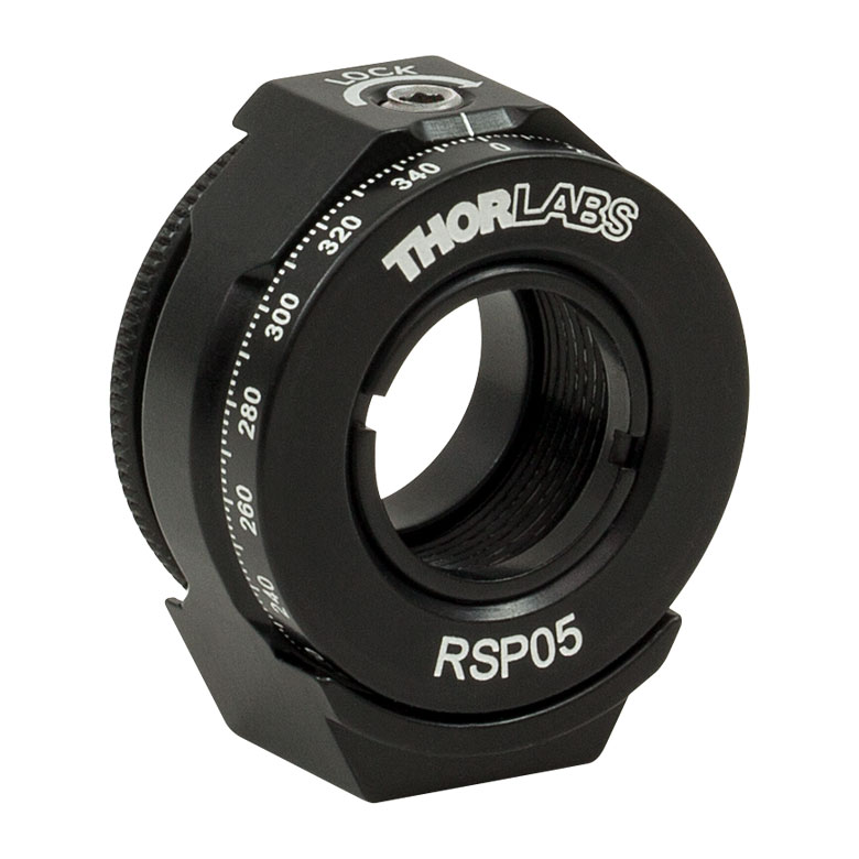
| Item # | MRM05(/M) | RSP05(/M) | CRM05 | PRM05(/M)a | SRM05 | KS05RS | CT104 |
| Click Photo to Enlarge |
 |
 |
 |
 |
 |
 |
 |
| Features | Mini Series | Standard | External SM1 (1.035"-40) Threads |
Micrometer | 16 mm Cage-Compatible | ±4° Kinematic Tip/Tilt Adjustment Plus Rotation | Compatible with 30 mm Cage Translation Stages and 1/4" Translation Stagesb |
| Additional Details | |||||||
| Rotation Mounts for Ø1" Optics | ||||||||
|---|---|---|---|---|---|---|---|---|
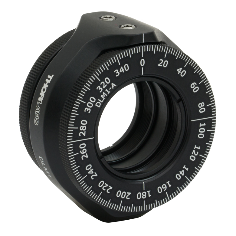
| Item # | RSP1(/M) | LRM1 | RSP1D(/M) | DLM1(/M) | CLR1(/M) | RSP1X15(/M) | RSP1X225(/M) | PRM1(/M)a |
| Click Photo to Enlarge |
 |
 |
 |
 |
 |
 |
|
 |
| Features | Standard | External SM1 (1.035"-40) Threads |
Adjustable Zero | Two Independently Rotating Carriages | Rotates Optic Within Fixed Lens Tube System |
Continuous 360° Rotation or 15° Increments |
Continuous 360° Rotation or 22.5° Increments |
Micrometer |
| Additional Details | ||||||||
| Rotation Mounts for Ø1" Optics | ||||||
|---|---|---|---|---|---|---|
| Item # | LM1-A & LM1-B(/M) |
CRM1T(/M) | CRM1LT(/M) | CRM1PT(/M) | KS1RS | K6XS |
| Click Photo to Enlarge |
  |
 |
 |
 |
 |
 |
| Features | Optic Carriage Rotates Within Mounting Ring | 30 mm Cage-Compatiblea | 30 mm Cage-Compatible for Thick Opticsa |
30 mm Cage-Compatible with Micrometera |
±4° Kinematic Tip/Tilt Adjustment Plus Rotation | Six-Axis Kinematic Mounta |
| Additional Details | ||||||
| Rotation Mounts for Ø2" Optics | |||||||
|---|---|---|---|---|---|---|---|
| Item # | RSP2(/M) | RSP2D(/M) | PRM2(/M) | LM2-A & LM2-B(/M) |
LCRM2A(/M) | KS2RS | K6X2 |
| Click Photo to Enlarge |  |
 |
 |
  |
 |
 |
 |
| Features | Standard | Adjustable Zero |
Micrometer | Optic Carriage Rotates Within Mounting Ring | 60 mm Cage-Compatible | ±4° Kinematic Tip/Tilt Adjustment Plus Rotation | Six-Axis Kinematic Mount |
| Additional Details | |||||||
| Rotation Drive Mechanism and Adjustment Range | Manual, 360° Continuous | Coarse: Manual, 360° Continuous; Fine: ±7° Micrometer |
Manual, 360° Continuous | ||||
| Optic Mounting | Internally SM2-Threaded Carriage | Internal SM2 Threads in LM2-A |
Internally SM2-Threaded Carriage | ||||
| Maximum Accepted Optic Thickness | 0.51" (13 mm) | 0.54" (13.7 mm) | 0.48" (12.2 mm) | 0.46" (11.7 mm) | 0.52" (13.2 mm) | 0.47" (12 mm) | 0.53" (13.4 mm) |
| Post Mounting | 8-32 (M4) Tap | 8-32 (M4) Tap in LM2-B | 8-32 (M4) Tap | Four Counterbores for 8-32 (M4) Cap Screws | Six Counterbores for 8-32 (M4) Cap Screws | ||
| Cage System Compatibility | N/A | Four 4-40 (M3) Taps on Rotation Dial with 60 mm Spacing |
N/A | Four Bores for Ø6 mm Cage Rods with 60 mm Spacing |
N/A | N/A | |
Manual Rotation Stages
| Manual Rotation Stages | ||||||
|---|---|---|---|---|---|---|
| Item # | RP005(/M) | PR005(/M) | MSRP01(/M) | RP01(/M) | RP03(/M) | QRP02(/M) |
| Click Photo to Enlarge |
 |
 |
 |
 |
 |
 |
| Features | Standard | Two Hard Stops | ||||
| Additional Details | ||||||
| Manual Rotation Stages | ||||||
|---|---|---|---|---|---|---|
| Item # | XRNR1(/M) | XRR1(/M) | PR01(/M) | CR1(/M) | XYR1(/M) | OCT-XYR1(/M) |
| Click Photo to Enlarge |
 |
 |
 |
 |
 |
 |
| Features | Fine Rotation Adjuster and 2" Wide Dovetail Quick Connect |
Fine Rotation Adjuster and 3" Wide Dovetail Quick Connect |
Fine Rotation Adjuster and SM1-Threaded Central Aperture |
Fine Pitch Worm Gear | Rotation and 1/2" Linear XY Translation | |
| Additional Details | ||||||
Motorized Rotation Mounts and Stages
| Motorized Rotation Mounts and Stages with Central Clear Apertures | |||||
|---|---|---|---|---|---|
| Item # | DDR25(/M) | PDR1C(/M) | PDR1(/M) | PDR1V(/M) | PDXR1(/M) |
| Click Photo to Enlarge |
 |
 |
 |
 |
 |
| Features | Compatible with SM05 Lens Tubes, 16 mm Cage System, & 30 mm Cage System |
Compatible with 16 mm Cage System |
Compatible with SM05 Lens Tubes & 30 mm Cage System |
Vacuum-Compatible; Also Compatible with SM05 Lens Tubes & 30 mm Cage System |
Compatible with SM05 Lens Tubes & 30 mm Cage System |
| Additional Details | |||||
| Motorized Rotation Mounts and Stages with Central Clear Apertures | |||||
|---|---|---|---|---|---|
| Item # | K10CR1(/M) | PRM1Z8(/M)a | DDR100(/M) | ELL14 | HDR50(/M) |
| Click Photo to Enlarge |
 |
 |
 |
 |
 |
| Features | Compatible with SM1 Lens Tubes & 30 mm Cage System | Compatible with SM1 Lens Tubes, 16 mm Cage System, 30 mm Cage System |
Compatible with SM1 Lens Tubes, Open Frame Design for OEM Applications |
Compatible with SM2 Lens Tubes |
|
| Additional Details | |||||
| Motorized Rotation Mounts and Stages with Tapped Platforms | ||
|---|---|---|
| Item # | PRMTZ8(/M)a | ELL18(/M)b |
| Click Photo to Enlarge |
 |
 |
| Features | Tapped Mounting Platform for Mounting Prisms or Other Optics | Tapped Mounting Platform, Open Frame Design for OEM Applications |
| Additional Details | ||

 Zoom
Zoom
Click for Details
RP005(/M) Mechanical Diagram


- 360° Continuous Rotation
- Laser-Engraved Graduation Marks at 2° Increments and Witness Line
- Mounting Platform Height: 0.67"
- Platform Mounting Taps: 4-40 (M3) and 1/4"-20 (M6)
- Load Capacity: 40 lbs (18 kg) with Stage Mounted on a Horizontal Surface
- Four 1/4" (M6) Clearance Holes to Mount to Optical Tables or Breadboards
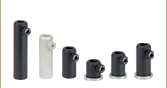
Thorlabs' RP005(/M) Manual Rotation Stage has a Ø1" rotating platform and is ideal for smaller optomechnical components requiring smooth, backlash-free rotation. The stage offers 360º of continuous rotation with a scale that is engraved in 2° increments along the side of the rotating platform. The scale is marked every 30° by a number directly under its corresponding tick mark. Rotation can be locked by tightening the side-located setscrew using a 5/64" (2.0 mm) balldriver or hex key. Do not remove the locking setscrew from the stage; doing so can permanently reduce locking performance.
The rotating platform contains six 4-40 (M3) taps, for smaller components such as cage cube optic mounts or mini-series posts, and one, central 1/4"-20 (M6) tap for larger components such as Ø1/2" or Ø1" post assemblies. Additionally, the top platform includes two Ø0.13" holes for mounting Thorlabs' FiberBench optic mounts, wave plate modules, polarization modules, and alignment tools. A setscrew with a 0.05" (1.5 mm) hex on the side of the rotating platform locks the FiberBench accessory in place.
Four 1/4" (M6) clearance holes are included in the base to mount the stage to an optical table or breadboard. When mounted on a horizontal surface, the stage can support a load up to 40 lbs (18 kg).

 Zoom
Zoom
Click for Details
MSRP01(/M) Mechanical Diagram

- 360° Continuous Rotation
- Laser-Engraved Graduation Marks at 2° Increments and 20 arcmin Vernier Scale
- Mounting Platform Height: 0.51"
- Platform Mounting Taps: 4-40 (M3) and 8-32 (M4)
- Load Capacity:
- 50 lbs (22 kg) with Stage Mounted on Horizontal Surface
- 1.3 N·m Maximum Horizontal Torque
- Four #4 (M3) Clearance Holes to Mount to Optical Tables or Breadboards
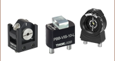
Thorlabs' MSRP01(/M) Manual Mini-Series Rotation Stage has a Ø1.4" rotating platform and provides smooth, backlash-free rotation utilizing two precision bearings. The stage offers 360º of continuous rotation with a scale that is engraved in 2° increments along the outer circumference of the rotating platform. It is marked every 20° by a number directly under its corresponding tick mark and includes a 20 arcmin Vernier scale. Rotation can be locked by tightening the side-located setscrew using a 0.05" (1.3 mm) balldriver or hex key.
The rotating platform contains four 4-40 (M3) taps and one central 8-32 (M4) tap for mini-series posts and accessories or our miniature dovetail stages, as shown in the image above.
Four #4 (M3) clearance holes are included in the base to mount the stage to a mini-series breadboard. A side-located 4-40 (M3) mounting hole is included to mount the stage vertically. It has a maximum torque capacity of 1.3 N·m when mounted in this configuration. When mounted on a horizontal surface, the stage can support a load up to 50 lbs (22 kg).

 Zoom
Zoom
Click for Details
RP01(/M) Mechanical Diagram

- 360° Continuous Rotation
- Laser-Engraved Graduation Marks at 2° Increments and Witness Line
- Mounting Platform Height: 0.63"
- Platform Mounting Taps: 8-32 (M4) and 1/4"-20 (M6)
- Load Capacity:
- 110 lbs (50 kg) with Stage Mounted on Horizontal Surface
- 9 lbs (4 kg) with Stage Mounted on Vertical Surface
- Four 1/4" (M6) Clearance Holes to Mount to Optical Tables or Breadboards
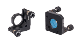
Thorlabs' RP01(/M) Manual Rotation Stage has a Ø2" rotating platform and is ideal for larger optomechnical components requiring smooth, backlash-free rotation. The stage offers 360º of continuous rotation with a scale that is engraved in 2° increments along the outer circumference of the rotating platform. It is marked every 20° by a number directly under its corresponding tick mark. Rotation can be locked by tightening the side-located setscrew using a 5/64" (2.0 mm) balldriver or hex key.
The rotating platform contains four 8-32 (M4) taps and one central 1/4"-20 (M6) tap for larger assemblies such as Ø1/2" or Ø1" post assemblies and optomechanical mounts, as shown in the image to the right.
Four 1/4" (M6) clearance holes are included in the base to mount the stage to an optical table or breadboard. A side-located 8-32 (M4) mounting hole is included to mount the stage vertically. It has a maximum load capacity of 9 lbs (4 kg) when mounted in this configuration. When mounted on a horizontal surface, the stage can support a load up to 110 lbs (50 kg).

 Zoom
Zoom
Click for Details
RP03(/M) Mechanical Diagram
(The RP03/M will have M4 taps in place of the 6-32 taps shown in the above diagram.)

- 360° Continuous Rotation
- Laser-Engraved Graduation Marks at 1° Increments and Witness Line
- Mounting Platform Height: 0.70" (17.8 mm)
- Platform Mounting Taps:
- RP03: 6-32, 8-32 and 1/4"-20
- RP03/M: M4 and M6
- Load Capacity:
- 175 lbs (80 kg) with Stage Mounted on Horizontal Surface
- 50 lbs (22 kg) with Stage Mounted on Vertical Surface
- Four 1/4" (M6) Clearance Holes to Mount to Optical Tables or Breadboards
Thorlabs' RP03(/M) Manual Rotation Stage has a Ø4.3" rotating platform and is ideal for larger optomechnical components requiring smooth, backlash-free rotation. The stage offers 360º of continuous rotation with a scale that is engraved in 1° increments along the outer circumference of the rotating platform. It is marked every 20° by a number directly under its corresponding tick mark. Rotation can be locked by tightening the side-located setscrew using a 5/64" (2.0 mm) balldriver or hex key.
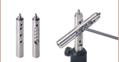
The imperial RP03 rotating platform contains eight 6-32, sixteen 8-32, and thirteen 1/4"-20 taps. The metric RP03/M rotating platform contains twenty-four M4 and thirteen M6 taps. The 6-32 taps can be used with our PM3 and PM4 Clamping Arms, while the M4 taps can be used with our PM3/M and PM4/M Clamping Arms. This allows you to clamp small to large componens onto the rotating platform, as shown in the image above and to the right. The 8-32, M4, 1/4"-20, and M6 taps can all be used to secure larger systems, such as a manual or motorized translation stage or post assembly.
Four 1/4" (M6) clearance holes are included in the base to mount the stage to an optical table or breadboard. Three side-located 8-32 (M4) mounting holes are included to mount the stage vertically. It has a maximum load capacity of 50 lbs (22 kg) when mounted in this configuration. When mounted on a horizontal surface, the stage can support a load up to 175 lbs (79 kg).