Cerna® Mini Microscopes
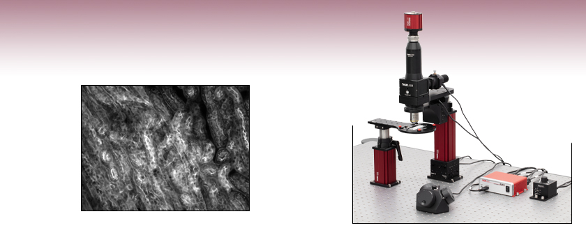
- Quick and Easy Installation
- Ideal for Sample Preparation, Imaging, and Inspection
- 6" Throat Depth Accommodates Large Samples
- Easily Adaptable to Changing Imaging Needs
SFMGFP2
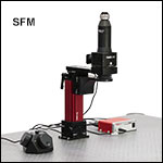
The Cerna® Mini Microscope uses an open-frame design to maximize space for experiments.
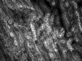
Mouse Kidney Cells Labeled with Alexa Fluor 488® Wheat Germ
Agglutinin Imaged with Cerna® Mini Microscope
Rigid Sample Holder Stand and Optical Table Not Included

Please Wait
Click to Enlarge
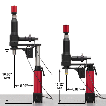
The objective height of the Cerna mini microscope can be manually adjusted over a range of 6.38". A motorized objective holder provides 1" of fine Z focus control.
Features
- Cerna® Mini Microscopes for Widefield or Fluorescence Imaging and Photonic Integrated Circuit Alignment/Testing
- User-Configurable Versions Allow for User-Supplied Components
- Preconfigured Versions Ready for Imaging Right Out of the Box
- Accepts C-Mount Cameras from Thorlabs and Other Major Manufacturers
- 6" Throat Depth and Open Frame Design Maximizes Space for Large Samples
- 1" of Fine Motorized Motion in X, Y, and Z
- Objective Nosepiece has M32 x 0.75 Threads
- Adapter for M25 x 0.75 Objective Threads Included
- Easily Integrate Custom Modules to Microscope's XT66 Rail Body
Thorlabs' Cerna Mini Microscopes are designed to support widefield, widefield fluorescence, or reflected light imaging. They can also be used for the alignment and testing of photonic integrated circuits (PICs). They are quick to set up and simple to use. We offer user-configurable microscopes, which are the basic system with no add-ons included, as well as preconfigured microscopes, which are fully outfitted for imaging right out of the box.
There are three types of Cerna mini microscopes. User-configurable microscopes, Item #'s SFM2 and SFM, are designed for users to integrate their own scientific camera, objective, illumination source, fluorescence filter set, and filter cube. The SFM2 supports widefield imaging, while the SFM, which includes an epi-illuminator module, supports epi-fluorescence imaging. The SFMGFP2 is our preconfigured microscope. It is designed for epi-fluorescence imaging of Green Fluorescence Protein (GFP) right out of box and includes a 470 nm LED with SFM80 collimation module, fluorescence filter set for GFP, and 10X objective. The SFMGFP2 microscope system includes a 2.1 megapixel sCMOS scientific camera.
Each microscope has a deep 6" throat depth and slim 3" wide design to provide ample space around the objective for adding sample stages, perfusion equipment, or other experimental apparatus. The motorized stepper motor stage can move the entire microscope 1" in X and Y. The nosepiece height can be manually adjusted to provide up to 16.70" of clearance for large samples, as shown in the photos to the right. The objective holder has up to 1" of motorized focusing adjustment.
These microscopes are compatible with all of Thorlabs' scientific cameras because each is equipped with a 1X camera tube with C-Mount (1.00"-32) threads. The camera port also features 4.1 mm of focus adjustment, which can be easily set by turning the silver knurled ring at the top of the camera tube.
The epi-illuminator module, included with all microscopes except the SFM2, accepts one of two collimation modules (available below) designed for Thorlabs' mounted LEDs, and can be easily modified to accept two collimation modules by replacing the epi-illuminator spacer block at the rear of the unit with a DFM1(/M) filter cube, C4W-CC cage cube connector, and an SM1CP2 end cap.
In order to minimize the footprint on the table and maximize the throat depth, the base of these microscopes must be bolted to an optical table or breadboard to remain upright. The microscope can be mounted to the MB1224 (MB3060/M) 12" x 24" (300 mm x 600 mm) breadboard to create a free-standing, portable system.
Accessories and Upgrades
To allow the experimenter to use a single microscope for samples that require different imaging configurations, these microscopes feature a modular design that allows light sources, filter cubes, cameras, and eyepieces to be easily added or exchanged. This design allows one Cerna mini microscope to be adapted for many applications from patch clamping to fluorescence imaging in live samples, all while taking up minimal space in the lab. Compatible modules are offered separately below.
Thorlabs' rigid stands (available separately) can be used to position microscope slides, well plates, petri dishes, micromanipulators, and other experimental apparatus underneath the objective, allowing the microscope to be used for both in vivo and in vitro imaging applications. The stands are easy to install and remove, allowing the microscope to be quickly adapted from imaging slices to examining intact samples.
DIY Customization
For the DIY builder, the body of each Cerna mini microscope uses a section of 66 mm rail and a Ø1.5" optical post, allowing users to integrate custom modules built from our extensive catalog of optomechanics. Microscopes with an epi-illuminator module have four 4-40 taps for compatibility with our 30 mm cage system, supporting the integration of custom illumination sources. We also offer several adapters (available below) that combine a D1N dovetail with standard cage system and lens tube mounting features for users interested in adding custom camera ports or additional epi-illuminator modules. Additionally, we have trinocular port adapters, designed to allow trinoculars to be used with DIY Cerna systems. For integrating a transmitted light module, we have our 66 mm rail carriage, optomechanical mounts, and mounted LEDs.
| Quick Links | |||||||||
|---|---|---|---|---|---|---|---|---|---|
| Cerna Mini Microscope Systems | Accessories | ||||||||
| User Configurable Cerna Mini Microscopes |
Preconfigured Cerna Mini Microscopes |
LED Collimation Modules |
Filter Cube | Upright Trinoculars |
Camera Tubes | Double Camera Ports |
Dovetail Adapters |
Epi-Illuminator Module |
|
| Microscope Body | |
|---|---|
| Rail Length | 174.3 mm (6.86") |
| Post Length | 200 mm (7.87") |
| Throat Depth | 6.00" (152.4 mm) |
| Manual Height Adjustment | 6.38" (161.9 mm) |
| Motorized Motion | 1" Microscope Travel in X and Y 1" Z Motion of Objective Stage |
| Nosepiece Threading | Internal M32 x 0.75, M32M25S Included for M25 x 0.75 Threaded Objectives |
| Mounting Screws | 1/4"-20 or M6, 8 of Each Type Included |
| Breadboard (Not Included) | MB1224 12" x 24" Breadboard or MB3060/M 300 mm x 600 mm Breadboard |
| Camera Port | |
|---|---|
| Item # | WFA4100 |
| Magnificationa | 1X |
| Dovetail | Male D1N |
| Tube Lens Focal Lengtha | 200 mm |
| Camera Threading | C-Mount (1.00"-32) |
| Motorized Translation Stages (XYZ Motion)a | |
|---|---|
| Translation Range | 25.4 mm (1") |
| Bidirectional Repeatability | 5 μm |
| Backlash | 10 μm |
| Minimum Incremental Movement | 424 nm |
| Minimum Achievable Repeatable Movement | 1.06 μm |
| Velocity (Max) | 7 mm/s |
| Acceleration (Max) | 11 mm/s² |
| Cable Length | 6' (1.8 m) |
| Load Capacitya | |
| Stepper Motor Specifications |
| Motion Controller | |
|---|---|
| Item # | MCM301 |
| Motor Output | |
| Motor Drive Voltage | 24 V |
| Motor Drive Current | 7.0 A (Peak) 3.0 A (RMS) |
| Motor Drive Type | 12-Bit PWM Control |
| Control Algorithm | Open/Closed-Loop Microstepping |
| Stepping | 128 Microsteps per Full Step |
| Position Feedback | Quadrature Encoder (QEP) Input, 5 V |
| Encoder Feedback Bandwidth | 1 MHz |
| Position Counter | 32 Bit |
| Operating Modes | Position and Velocity |
| Velocity Profile | Trapezoid |
| Motor Drive Connector |
| Input Power Requirements |
| General |
| LED Collimation Package (Only Included with SFMGFP2) | |
|---|---|
| Item # | SFM80 |
| Compatible LED Divergence Angles | 80° to 120° |
| Operating Wavelength Range | 350 to 700 nm |
| T-Cube™ LED Drivera (Only Included with SFMGFP2) | |
|---|---|
| Item # | LEDD1B (LED Driver) KPS201 (Power Supply) |
| General | |
| Output Current Range | 0 to 1200 mA |
| LED Current Limit Set Point Range | 200 to 1200 mA |
| LED Forward Voltage | 11 V (Min) 12 V (Typical) |
| Current Ripple | 8 mA |
| Current Ripple Frequency | 570 kHz |
| Modulation Modeb |
| Trigger Modeb |
| General Data |
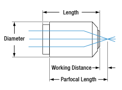
Objective Dimensions
| Objective (Only Included with SFMGFP2) | |
|---|---|
| Item # | N10X-PF |
| Magnification | 10X |
| Manufacturer Part # | MRH00101 |
| Numerical Aperture (NA) | 0.30 |
| Working Distance (WD)a | 16 mm |
| Parfocal Lengtha | 60 mm |
| Design Tube Lens Focal Length | 200 mm |
| Coverslip Correction | 0.17 mm |
| Barrel Diametera | 30.0 mm |
| Lengtha | 48.7 mm |
| Threading | M25 x 0.75 External Threads |
| Scientific Cameraa (Only Included with SFMGFP2) | |
|---|---|
| System | SFMGFP2 |
| Item # | CS2100M-USB |
| Sensor | Monochrome sCMOS |
| Effective Number of Pixels (Horizontal x Vertical) | 1920 x 1080 |
| Imaging Area (Horizontal x Vertical) | 9.68 mm x 5.44 mm |
| Pixel Size | 5.04 µm x 5.04 µm |
| Optical Format | 2/3" Format (11 mm Diagonal) |
| Peak Quantum Efficiency | 61% at 600 nm |
| Quantum Efficiency (Click for Graph) | Click for Data |
| IR-Blocking Filter Transmission (Click for Graph) |
N/A |
| Exposure Time | 0.029 ms to 7767.2 ms in ~0.03 ms Increments |
| Pixel Clock Speed | 74.25 MHz to 148.5 MHz |
| Analogue-to-Digital Converter Resolution | 16 Bit |
| Analog-to-Digital Converter Gain | N/A |
| Optical Black Clamp | N/A |
| Vertical Hardware Binning | Continuous Integer Values from 1 to 16b |
| Horizontal Software Binning | Continuous Integer Values from 1 to 16b |
| Region of Interest | 8 x 2 Pixelsc to 1920 x 1080 Pixels, Rectangular |
| Read Noise | <1 e- Mediand |
| Digital Output | 16 Bit |
| Host PC Interface | USB 3.0 |
| Lens Mount | C-Mount (1.000"-32) |
ThorCam™
ThorCam is a powerful image acquisition software package that is designed for use with our cameras on 32- and 64-bit Windows® 7, 10, or 11 systems. This intuitive, easy-to-use graphical interface provides camera control as well as the ability to acquire and play back images. Single image capture and image sequences are supported. Please refer to the screenshots below for an overview of the software's basic functionality.
Application programming interfaces (APIs) and a software development kit (SDK) are included for the development of custom applications by OEMs and developers. The SDK provides easy integration with a wide variety of programming languages, such as C, C++, C#, Python, and Visual Basic .NET. Support for third-party software packages, such as LabVIEW, MATLAB, and µManager* is available. We also offer example Arduino code for integration with our TSI-IOBOB2 Interconnect Break-Out Board.
*µManager control of 1.3 MP Kiralux cameras is not currently supported.
| Recommended System Requirementsa | |
|---|---|
| Operating System | Windows® 7, 10, or 11 (64 Bit) |
| Processor (CPU)b | ≥3.0 GHz Intel Core (i5 or Higher) |
| Memory (RAM) | ≥8 GB |
| Hard Drivec | ≥500 GB (SATA) Solid State Drive (SSD) |
| Graphics Cardd | Dedicated Adapter with ≥256 MB RAM |
| Motherboard | USB 3.0 (-USB) Cameras: Integrated Intel USB 3.0 Controller or One Unused PCIe x1 Slot (for Item # USB3-PCIE) GigE (-GE) Cameras: One Unused PCIe x1 Slot |
| Connectivity | USB or Internet Connectivity for Driver Installation |
Example Arduino Code for TSI-IOBOB2 Board
Click the button below to visit the download page for the sample Arduino programs for the TSI-IOBOB2 Shield for Arduino. Three sample programs are offered:
- Trigger the Camera at a Rate of 1 Hz
- Trigger the Camera at the Fastest Possible Rate
- Use the Direct AVR Port Mappings from the Arduino to Monitor Camera State and Trigger Acquisition
Click the Highlighted Regions to Explore ThorCam Features
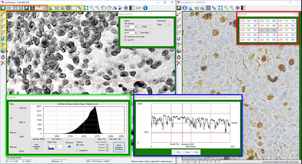
Camera Control and Image Acquisition
Camera Control and Image Acquisition functions are carried out through the icons along the top of the window, highlighted in orange in the image above. Camera parameters may be set in the popup window that appears upon clicking on the Tools icon. The Snapshot button allows a single image to be acquired using the current camera settings.
The Start and Stop capture buttons begin image capture according to the camera settings, including triggered imaging.
Timed Series and Review of Image Series
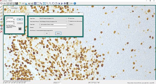
The Timed Series control, shown in Figure 1, allows time-lapse images to be recorded. Simply set the total number of images and the time delay in between captures. The output will be saved in a multi-page TIFF file in order to preserve the high-precision, unaltered image data. Controls within ThorCam allow the user to play the sequence of images or step through them frame by frame.
Measurement and Annotation
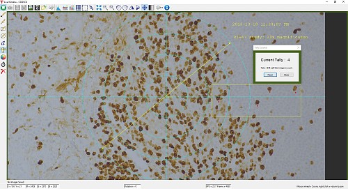
As shown in the yellow highlighted regions in the image above, ThorCam has a number of built-in annotation and measurement functions to help analyze images after they have been acquired. Lines, rectangles, circles, and freehand shapes can be drawn on the image. Text can be entered to annotate marked locations. A measurement mode allows the user to determine the distance between points of interest.
The features in the red, green, and blue highlighted regions of the image above can be used to display information about both live and captured images.
ThorCam also features a tally counter that allows the user to mark points of interest in the image and tally the number of points marked (see Figure 2). A crosshair target that is locked to the center of the image can be enabled to provide a point of reference.
Third-Party Applications and Support
ThorCam is bundled with support for third-party software packages such as LabVIEW, MATLAB, and .NET. Both 32- and 64-bit versions of LabVIEW and MATLAB are supported. A full-featured and well-documented API, included with our cameras, makes it convenient to develop fully customized applications in an efficient manner, while also providing the ability to migrate through our product line without having to rewrite an application.
Click to Enlarge
Figure 1: A timed series of 10 images taken at 1 second intervals is saved as a multipage TIFF.
Click to Enlarge
Figure 2: A screenshot of the ThorCam software showing some of the analysis and annotation features. The Tally function was used to mark four locations in the image. A blue crosshair target is enabled and locked to the center of the image to provide a point of reference.
Performance Considerations
Please note that system performance limitations can lead to "dropped frames" when image sequences are saved to the disk. The ability of the host system to keep up with the camera's output data stream is dependent on multiple aspects of the host system. Note that the use of a USB hub may impact performance. A dedicated connection to the PC is preferred. USB 2.0 connections are not supported.
First, it is important to distinguish between the frame rate of the camera and the ability of the host computer to keep up with the task of displaying images or streaming to the disk without dropping frames. The frame rate of the camera is a function of exposure and readout (e.g. clock, ROI) parameters. Based on the acquisition parameters chosen by the user, the camera timing emulates a digital counter that will generate a certain number of frames per second. When displaying images, this data is handled by the graphics system of the computer; when saving images and movies, this data is streamed to disk. If the hard drive is not fast enough, this will result in dropped frames.
One solution to this problem is to ensure that a solid state drive (SSD) is used. This usually resolves the issue if the other specifications of the PC are sufficient. Note that the write speed of the SSD must be sufficient to handle the data throughput.
Larger format images at higher frame rates sometimes require additional speed. In these cases users can consider implementing a RAID0 configuration using multiple SSDs or setting up a RAM drive. While the latter option limits the storage space to the RAM on the PC, this is the fastest option available. ImDisk is one example of a free RAM disk software package. It is important to note that RAM drives use volatile memory. Hence it is critical to ensure that the data is moved from the RAM drive to a physical hard drive before restarting or shutting down the computer to avoid data loss.
| Simple Fluorescence Microscopes Shipping List | |||
|---|---|---|---|
| Item # | SFM2 | SFM | SFMGFP2 |
| Microscope Body with PLSXY Stage and Motorized Objective Mount | 1 | 1 | 1 |
| 3-Axis Controller (MCM301) | 1 | 1 | 1 |
| 3-Knob USB HID Joystick (MCMK3) | 1 | 1 | 1 |
| 1X Camera Port with 200 mm Focal Length Tube Lens (WFA4100) | 1 | 1 | 1 |
| Epi-Illuminator Cube Housing (WFA2002) | - | 1 | 1 |
| OEM Microscopy Filter Cube (MDFM-MF2) | - | - | 1 |
| GFP/Alexa Fluor 488 Filter Set (MDF-GFP) | - | - | 1 |
| T-Cube™ LED Driver (LEDD1B) | - | - | 1 |
| T-Cube™ Power Supply (KPS201) | - | - | 1 |
| Blue (470 nm) LED (M470L5) | - | - | 1 |
| 80° Collimating Tube with XY Adjustment (SFM80) | - | - | 1 |
| Monochrome UBS 3.0 sCMOS Camera (CS2100M-USB) | - | - | 1 |
| 10X Nikon Plan Fluorite Imaging Objective (N10X-PF) | - | - | 1 |
| M6 Socket Head Cap Screw | 6 | 8 | 8 |
| 1/4"-20 Socket Head Cap Screw | 6 | 8 | 8 |
| M6 Flat Washer | 6 | 8 | 8 |
| LED Driver Operating Manual | - | - | 1 |
| Thorlabs Digital Camera Quick Start Guide | - | - | 1 |
| ThorCam Camera Software CD | - | - | 1 |
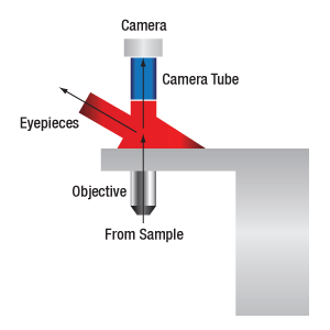
When viewing an image with a camera, the system magnification is the product of the objective and camera tube magnifications. When viewing an image with trinoculars, the system magnification is the product of the objective and eyepiece magnifications.
| Manufacturer | Tube Lens Focal Length |
|---|---|
| Leica | f = 200 mm |
| Mitutoyo | f = 200 mm |
| Nikon | f = 200 mm |
| Olympus | f = 180 mm |
| Thorlabs | f = 200 mm |
| Zeiss | f = 165 mm |
Magnification and Sample Area Calculations
Magnification
The magnification of a system is the multiplicative product of the magnification of each optical element in the system. Optical elements that produce magnification include objectives, camera tubes, and trinocular eyepieces, as shown in the drawing to the right. It is important to note that the magnification quoted in these products' specifications is usually only valid when all optical elements are made by the same manufacturer. If this is not the case, then the magnification of the system can still be calculated, but an effective objective magnification should be calculated first, as described below.
To adapt the examples shown here to your own microscope, please use our Magnification and FOV Calculator, which is available for download by clicking on the red button above. Note the calculator is an Excel spreadsheet that uses macros. In order to use the calculator, macros must be enabled. To enable macros, click the "Enable Content" button in the yellow message bar upon opening the file.
Example 1: Camera Magnification
When imaging a sample with a camera, the image is magnified by the objective and the camera tube. If using a 20X Nikon objective and a 0.75X Nikon camera tube, then the image at the camera has 20X × 0.75X = 15X magnification.
Example 2: Trinocular Magnification
When imaging a sample through trinoculars, the image is magnified by the objective and the eyepieces in the trinoculars. If using a 20X Nikon objective and Nikon trinoculars with 10X eyepieces, then the image at the eyepieces has 20X × 10X = 200X magnification. Note that the image at the eyepieces does not pass through the camera tube, as shown by the drawing to the right.
Using an Objective with a Microscope from a Different Manufacturer
Magnification is not a fundamental value: it is a derived value, calculated by assuming a specific tube lens focal length. Each microscope manufacturer has adopted a different focal length for their tube lens, as shown by the table to the right. Hence, when combining optical elements from different manufacturers, it is necessary to calculate an effective magnification for the objective, which is then used to calculate the magnification of the system.
The effective magnification of an objective is given by Equation 1:
 |
(Eq. 1) |
Here, the Design Magnification is the magnification printed on the objective, fTube Lens in Microscope is the focal length of the tube lens in the microscope you are using, and fDesign Tube Lens of Objective is the tube lens focal length that the objective manufacturer used to calculate the Design Magnification. These focal lengths are given by the table to the right.
Note that Leica, Mitutoyo, Nikon, and Thorlabs use the same tube lens focal length; if combining elements from any of these manufacturers, no conversion is needed. Once the effective objective magnification is calculated, the magnification of the system can be calculated as before.
Example 3: Trinocular Magnification (Different Manufacturers)
When imaging a sample through trinoculars, the image is magnified by the objective and the eyepieces in the trinoculars. This example will use a 20X Olympus objective and Nikon trinoculars with 10X eyepieces.
Following Equation 1 and the table to the right, we calculate the effective magnification of an Olympus objective in a Nikon microscope:
 |
The effective magnification of the Olympus objective is 22.2X and the trinoculars have 10X eyepieces, so the image at the eyepieces has 22.2X × 10X = 222X magnification.
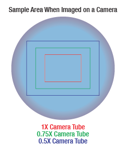
Sample Area When Imaged on a Camera
When imaging a sample with a camera, the dimensions of the sample area are determined by the dimensions of the camera sensor and the system magnification, as shown by Equation 2.
 |
(Eq. 2) |
The camera sensor dimensions can be obtained from the manufacturer, while the system magnification is the multiplicative product of the objective magnification and the camera tube magnification (see Example 1). If needed, the objective magnification can be adjusted as shown in Example 3.
As the magnification increases, the resolution improves, but the field of view also decreases. The dependence of the field of view on magnification is shown in the schematic to the right.
Example 4: Sample Area
The dimensions of the camera sensor in Thorlabs' previous-generation 1501M-USB Scientific Camera are 8.98 mm × 6.71 mm. If this camera is used with the Nikon objective and trinoculars from Example 1, which have a system magnification of 15X, then the image area is:
 |
Sample Area Examples
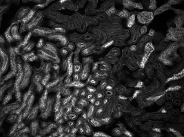
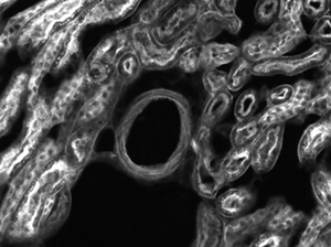
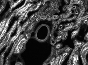
The images of a mouse kidney below were all acquired using the same objective and the same camera. However, the camera tubes used were different. Read from left to right, they demonstrate that decreasing the camera tube magnification enlarges the field of view at the expense of the size of the details in the image.
| Posted Comments: | |
| No Comments Posted |

Click to Enlarge
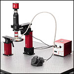
The OSL2 (shown here with the OSL2RFB gooseneck bundle) can be used to illuminate samples viewed with the Cerna Mini Microscope. Here, the SFM2 microscope is shown with a
TL10X-2P microscope objective.
| Included Componentsa | |
|---|---|
| SFM2 | SFM |
| Microscope Body with Motorized 2D Translation Stage | |
| 1X Camera Tube with 200 mm Focal Length Tube Lens | |
| - | Epi-Illuminator Module |
| Motorized Objective Focusing Module | |
- SFM2 Requires User Supplied:
- SFM Requires User Supplied:
- Mounted LED or Illumination Lamp
- LED Collimation Module (Available Below)
- Filter Cube (Available Below)
- Filter Set for Fluorescence or Reflected Light Imaging
- Objective
- Scientific Camera
- 1/4" (M6) Slots to Mount to an Optical Table or Breadboard (Not Included)
Our SFM2 and SFM user configurable microscopes allow the users to customize the microscope with their own illumination source, objective, and scientific camera. These microscopes accept objectives with M32 x 0.75 threads or accept objectives with M25 x 0.75 threads by using the included adapter. Each microscope has a 1X camera tube that features C-Mount threads, making it compatible with any of Thorlabs' scientific cameras. The SFM2 is designed to support widefield imaging, while the SFM includes the epi-illuminator module to support widefield fluorescence and reflected light imaging. The SFM has a complete epi-fluorescence path and users can select their own fluorescence filter set and filter cubes. Fluorescence filter cubes and collimation tubes for Thorlabs' mounted LEDs are provided below.

Click to Enlarge
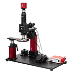
The SFMGFP2 with a Rigid Stand Slide Holder can be mounted on an MB1224 (MB3060/M) breadboard (not included), shown here with RDF1 rubber mounting feet.
Click to Enlarge
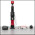
The Cerna Mini Microscopes have a slim 3" profile to maximize space for experimental setups.
- Ready for Epi-Fluorescence Imaging of Green Fluorescent Protein (GFP) Out of the Box
- Includes SFM System Described Above with the Following Accessories Installed:
- 1/4" (M6) Slots to Mount to an Optical Table or Breadboard (Not Included)
The SFMGFP2 uses the same optical pathway construction as the SFM above and is equipped with everything needed for imaging GFP or Alexa Fluor 488 fluorescence right out of the box. This includes a scientific camera, blue LED, GFP filter set, and 10X objective. This microscope provides 7.46" to 14.84" between the base of the microscope and the focal plane (including the manual 6.38" adjustment range and 1" of fine focus control). The provided fluorescence filter set and 470 nm LED enable imaging of GFP, Alexa Fluor 488, and other fluorophores of similar excitation/emission wavelengths. Filter sets and mounted LEDs can be easily swapped out to support imaging of other fluorophores or reflected light imaging setups.
The SFMGFP2 comes with a 2.1 megapixel sCMOS camera that can be connected to a PC via a USB 3.0 port. The sCMOS camera sensor has low read noise and a large dynamic range, providing the power to resolve dim signals without overexposing robust signals in the same sample. This camera can be operated using the intuitive ThorCam Software package; see the Software tab for details.

Click to Enlarge
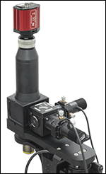
Two SFM80 LED collimation modules connected to the Cerna Mini Microscope with Epi-Illuminator Module using a DFM1(/M), C4W-CC, and SM1CP2.
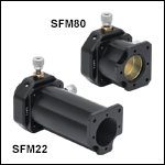
- Designed for Thorlabs' Mounted LEDs
- SFM22 Collimation Module
- <22° LED Divergence Angle
- Antireflection-Coated Optics for 400 - 700 nm
- SFM80 Collimation Module
- 80° to 120° LED Divergence Angle
- Antireflection-Coated Optics for 350 - 700 nm
These LED Collimation Modules are designed to allow our mounted LEDs to be connected to Cerna® Mini Microscopes with an Epi-Illuminator Module. Each collimation module connects to an LED via an XY translation mount with ±1 mm of travel, to allow the LED emitter to be centered on the optical axis. The SFM80 is designed for LEDs with an 80° to 120° divergence angle, while SFM22 is for LEDs with a divergence angle of <22°. The table below provides suggested ways to combine each LED mount with compatible mounted LEDs and fluorescence filter sets. Alternatively, the microscope can be set up for reflected light imaging by replacing the fluorescence filter set with a beamsplitter and polarizers. Thorlabs can also customize these modules to work with other LED divergence angles; please contact Tech Support with inquiries.
Each LED collimation module includes two 4-40 cap screws (3/32" hex) and two alignment pins for mounting the module on the epi-illuminator of an SFM or SFMGFP2 microscope. To create a two-LED epi-illuminator, replace the epi-illuminator spacer block on the Cerna mini microscope with a DFM1(/M) filter cube, C4W-CC cage cube connector, and an SM1CP2 end cap, as shown in the photo to the right. An SM1T2 lens tube coupler with two locking nuts is included for mounting LEDs that have internal SM1 threading.
| LED Collimation Module | Suggested LEDs | Recommended Fluorescence Filter Set | |||||||
|---|---|---|---|---|---|---|---|---|---|
| Item # | LED Divergence Angle | AR Coating Range | LED Item # | Spectruma | Color | Nominal Wavelength | Filter Set Item # | Design Fluorophore | Transmissionb |
| SFM22 | <22° | 400 - 700 nm | M430L4 | Violet | 430 nm | MDF-CFP | CFP | ||
| SFM80 | 80° to 120° | 350 - 700 nm | M385L3 | UV | 385 nm | MDF-BFP | BFP | ||
| M395L4 | UV | 395 nm | |||||||
| M505L4 | Cyan | 505 nm | MDF-YFP | YFP | |||||
| M530L4 | Green | 530 nm | MDF-TOM | tdTomato | |||||


Click to Enlarge
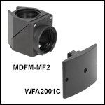
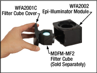
These filter cubes connect to the WFA2001C Epi-Illuminator Module Cover (one included with each SFM or SFMGFP2 microscope).
- Filter Cubes for Use with SFM and SFMGFP2 Microscopes
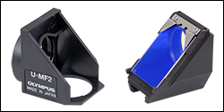
- MDFM-MF2 OEM Cube Assembly
- OEM Filter Cube from Olympus
- Plastic Construction
- WFA2001C: Extra Epi-Illuminator Module Cover to Aid in Quick Filter Exchanges
This Drop-In Filter Cube holds one Fluorescence Filter Set, which includes an excitation filter, emission filter, and dichroic mirror/beamsplitter. Optics can be mounted, aligned, and swapped out easily, following the videos and assembly instructions below.
The WFA2001C is an extra epi-illuminator module cover, allowing the filter cubes to be pre-mounted for quicker filter exchange.
Installation of Filters into the MDFM-MF2 Cube
| Compatible Filter Sizes | |
|---|---|
| Item # | MDFM-MF2 |
| Excitation Filter | Ø25 mm, Up to 5 mm Thick |
| Emission Filter | Ø25 mm, Up to 3.5 mm Thick |
| Dichroic | Up to 25.2 mm x 36.0 mm x 1.0 mm |
Click to Enlarge
MDFM-MF2 Retaining a Dichroic Beamsplitter

Click to Enlarge
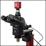
A Cerna Mini Microscope with Epi-Illuminator Module Configured with Trinoculars
Click for Details
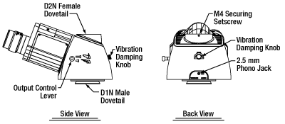
Drawing of LAURE1 and LAURE2 Trinoculars
- Ideal for Electrophysiology Applications
- 10X Eyepieces to Observe the FOV with the Naked Eye
- Available with or without IR Filters for Eye Protection
- Top-Located Port for Camera Attachment Using 0.5X, 0.7X, 0.75X, or 1X Camera Tube (Optional)
- See the Full Web Presentation for More Information
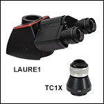
The LAURE1 and LAURE2 Trinoculars produce an upright image of a sample that can be viewed with the naked eye using the included 10X eyepieces or with a camera connected to the top-located camera port via a camera tube (camera and camera tube sold separately); this configuration is particularly useful for patch-clamping applications. A lever located on the side of the housing directs the incoming light to either the eyepieces or the camera. In order to protect the viewer's eyes, the LAURE1 trinoculars contain a filter before the eyepieces that blocks NIR light. This filter will not block NIR light that is sent to the camera port and it cannot be removed. To mount the trinoculars onto a Cerna® mini epi-fluorescence microscope, loosen the M4 setscrew at the top of the epi-illuminator module, remove the included camera tube, and replace it with the trinoculars. Tighten the M4 screw to lock the trinoculars in place.
These trinoculars incorporate several additional features. A red vibration damping knob on the side of the housing allows the detent mechanism on the carriage slider to be disengaged, which is useful for electrophysiology applications that require minimal vibration when switching between the eyepiece and camera port. These trinoculars also include a carriage position indicator switch via a 2.5 mm phono jack, allowing users to connect a laser interlock; it is designed to break the circuit in a laser interlock when the carriage is in the eyepiece output position. For custom-built optical detection systems, these trinoculars have 4-40 taps on the top D2N dovetail connector for compatibility with 30 mm cage systems and 4-40 taps on the bottom D1N dovetail for compatibility with 60 mm cage systems systems.
In order to use a C-mount camera with these trinoculars, a camera tube is required to position the camera at the image plane. The TC1X camera tube is compatible with the LAUREx trinoculars and does not introduce any magnification. It features C-mount threads for mounting scientific cameras and can be secured to the trinoculars via a dovetail and M3 setscrew.
System Magnification
The total system magnification will be the multiplicative product of the objective magnification and the eyepieces or camera tube magnification, depending on which is being used. To achieve an objective's stated magnification, the objective must have been designed for systems using a 200 mm tube lens. Please note that the eyepieces and camera will see a different FOV due to a difference in magnification in each path. Please see the Magnification & FOV tab for more information on objective's magnification dependence on the system's tube lens and how paths with differing magnifications will see a different FOV.

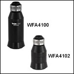
- One WFA4100 is Included with the Cerna® Mini Microscope
- Other Camera Tubes Offer Magnification
- WFA4101: 0.75X
- WFA4102: 0.5X
- C-Mount Threads for Camera Attachment
- 4.1 mm of Focus Adjustment for Camera
- See the Full Web Presentation for More Information
These camera tubes provide the mechanical spacing necessary to align a camera sensor to the imaging plane in a microscope. The top of each camera tube has external C-mount (1.00"-32) threading that accepts Thorlabs' scientific cameras, as well as cameras from most major manufacturers. In order to balance the size of the field of view (FOV) displayed on the camera against the resolution of the microscope, our camera tubes are offered in several magnifications from 1X to 0.5X. Greater magnification improves the resolution, but it also decreases the size of the FOV. Please see the Magnification & FOV tab for more information.
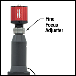
The WFA4100, one of which is included with the Cerna mini microscope, includes a 200 mm tube lens to focus the image from the objective at the sample plane with 1X magnification. The WFA4101 and WFA4102 camera tubes use a 150 mm or 100 mm focal length tube lens, respectively, to produce 0.75 times or 0.5 times the magnification of the objective. To compensate for mechanical tolerances or any alignment issue, these camera tubes also include an SM1ZM Fine Focus Adjuster directly before the camera. This is shown in the photo to the right.
System Magnification
The total system magnification will be the multiplicative product of the objective magnification and the eyepieces or camera tube magnification, depending on which is being used. To achieve an objective's stated magnification, the objective must have been designed for systems using a 200 mm tube lens. Please note that the eyepieces and camera will see a different FOV due to a difference in magnification in each path. Please see the Magnification & FOV tab for more information on objective's magnification dependence on the system's tube lens and how paths with differing magnifications will see a different FOV.

Click for Details
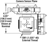
Mechanical Diagram of the 2CM2 Double Camera Port
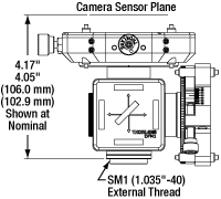
Click for Details
Mechanical Diagram of the 2CM1 Double Camera Port
| Compatible Filters | |||
|---|---|---|---|
| Type | Dimensions | Thickness | |
| Excitation | Ø25 mm | 5 mm | |
| Emission | Ø25 mm | 3.5 mm | |
| Dichroic | Min | 25.0 mm x 35.6 mm | 1.0 mm |
| Max | 25.2 mm x 36.0 mm | 2.0 mm | |
Click to Enlarge
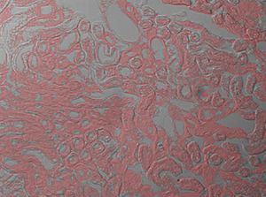
Live two-channel composite image generated using 2CM1 Mount, previous-generation scientific CCD cameras, and ThorCam software. The image shows Fluorescence (Pink) and DIC (Grayscale) images of a mouse kidney.
- Microscope Adapters Allow Two Scientific Cameras to Image a Single Optical Input Simultaneously
- Optics Not Included:
- Accepts 25 mm x 36 mm Dichroic Filters or Beamsplitters
- Accepts Standard Ø25 mm or Ø1" Filters on Outputs
- Fine Pitch Rotation and XY Adjustment for Image Co-Registration
- Coarse Focus Adjustment for Parfocalization of Cameras
- Can be Used with Inverted-Image Trinoculars or as Stand-Alone Double-Camera Ports
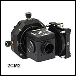
Thorlabs' two-camera mount are designed to attach two Thorlabs scientific cameras to a standard microscope, allowing simultaneous imaging of a single optical output. A rotation mount allows for 360° of rotational adjustment (±8° fine adjustment) for the reflected camera while a translation mount gives 4 mm linear XY adjustment of the transmitted camera. Both camera mounts have coarse focus adjustment by manually translating the cameras, allowing for parfocalization of both images. The 2CM1 and 2CM2 mounts have up to 15 mm and 11 mm of adjustment, respectively, using the cage rods, although this adjustment range may be limited by the geometry of the camera's front face.
Each mount includes a DFM1 fluorescence filter cube, which is designed to hold a fluorescence filter set (dichroic mirror, excitation filter, and emission filter) as well as plate beamsplitters or other similarly sized optics. See the table to the right for compatible optic sizes. The filter cube has an insert to hold filter set components with a kinematic design for easy swapping between mounted filter sets without requiring realignment. A DFM1T1 filter cube insert can also be used for mounting additional filter sets. Please note that these mounts do not include tube lenses.
These camera ports are ideal for use with Thorlabs' scientific cameras and ThorCam software. The 2CM1 mount is designed for cameras with 60 mm cage system taps on the front, such as our cooled sCMOS and CMOS cameras, while the 2CM2 mount is identical except for the inclusion of two LCP4S cage size adapters for compatibility with 30 mm cage system taps, such as those found on our compact scientific cameras with sCMOS and CMOS sensors. The ThorCam user interface, provided for free with our scientific cameras, includes a plug-in to allow for multiple live camera images to be overlaid into a real-time 2-channel composite, eliminating the need for frequent updates of a static overlay image. This live imaging method is ideal for applications such as calcium ratio imaging and electrophysiology.
To see example applications where these camera ports are used and how various filters and dichroics are used, please see the full presentation.
Cerna® Mini Microscope Compatibility
The input port of each camera port adapter has external SM1 (1.035"-40) threading and places Thorlabs scientific cameras' sensors at a distance of 4.05" to 4.17" (102.9 mm to 106.0 mm) from the base of the mount (see drawings to the upper right). An adapter can be mounted to a Cerna mini microscope with trinoculars or without trinoculars. These mounts are not compatible with the upright-image trinoculars.
Double Camera Port with Inverted-Image Trinoculars
These camera ports can be mounted directly onto our previous-generation inverted-image trinoculars using the SM1A58 adapter (available below). Simply screw the adapter onto the base of the camera port and install it onto the top port of the trinoculars in place of the camera tube. When used with the inverted-image trinoculars, each mounted camera will be parfocal with the eyepieces. When used with upright-image trinocs the camera sensors will not be parfocal with the eyepieces.
Stand-Alone Double Camera Port
The double camera port can be installed without trinoculars by connecting the WFA4111 Dovetail Adapter with a 200 mm focal length tube lens to the camera port using two lens tubes (SM2L10 and SM1M05) and an SM1A2 adapter. To mount this assembly onto the Cerna mini microscope, loosen the M4 setscrew at the top of the epi-illuminator module, remove the included camera tube, and replace it with the double camera port assembly. Tighten the M4 screw to lock the dovetail at the base of the WFA4111 adapter in place.

- Epi-Illumination Module Adapters
- Male D1N Dovetail Mates to Top of Cerna® Mini Epi-Illuminator Module
- Options for Compatibility with M38 x 0.5-Threaded, SM30-Threaded, and SM2-Threaded Components
- Options for Compatibility with 30 mm and 60 mm Cage Construction Systems
- Options for Direct Connection to Infinity-Corrected Tube Lenses
- Camera Port Adapter
- Male D2N and D2NB Dovetails Mate to Cerna® Trinoculars
- Internal SM1 (1.035"-40) and External SM2 Threads
- 30 mm Cage Compatible
Our Dovetail Adapters allow users to easily integrate custom assemblies that use our extensive line of optomechanical components with the Cerna mini microscope.
Epi-Illumination Module Adapters
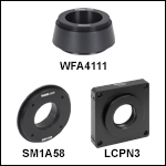
The WFA4111, SM2A59, LCPN2, LCPN3, and LCPN4 Adapters connect to the top of the Cerna mini microscope's epi-illumination module to allow custom built assemblies to be integrated in place of a camera tube or trinoculars. All four adapters utilize a male D1N dovetail to connect to the epi-illumination module.
The WFA4111 and SM2A59 adapters are designed for custom widefield viewing setups. The WFA4111 adapter features internal M38 x 0.5 threading, which is compatible with our SM38RR retaining rings to secure an optic inside the adapter. The internal threading also directly accepts our TTL200 and ITL200 tube lenses, while external SM2 (2.035"-40) threading on the top of the adapter allows it to be integrated into SM2 lens tube systems. The SM2A59 adapter features internal SM2 (2.035"-40) threading, which can directly accept our SM2-threaded infinity-corrected tube lenses for widefield imaging. Alternatively, the internal SM2 threading can be used to integrate with our SM2 lens tube systems for the construction of custom image detection modules.
The LCPN2 and LCPN3 adapters feature internal SM30 (M30.5 x 0.5) threading for Ø30 mm lens tubes; two SM30RR retaining rings are included to secure an optic inside the adapter. Four through holes, each with two side-located locking setscrews (5/64" [2 mm] hex), can be used to attach Ø6 mm cage rods for 60 mm cage systems. The LCPN2 adapter is designed to be used with custom widefield viewing setups and includes additional 4-40 tapped holes on 30 mm centers on the side opposite the dovetail for 30 mm cage systems. The LCPN3 adapter features a female D5Y dovetail to allow Olympus trinoculars with a male D5Y dovetail to be used with the Cerna Mini Microscope.
The LCPN4 adapter is also designed to be used with custom widefield viewing setups. It features SM2 (2.035"-40) threading for SM2 lens tubes and includes one SM2RR retaining ring for securing an optic. It has four through holes, each with a side-located locking setscrew (5/64" [2 mm] hex), that can be used to attach Ø6 mm cage rods for 60 mm cage systems.
Camera Port Adapter
The SM1A58 Camera Port Adapter has male D2N and D2NB dovetails and internal SM1 (1.035"-40) threads that allow a double camera port to be added to inverted-image trinoculars. External SM2 threads and taps for our 30 mm cage system also support the construction of custom modules.

Click to Enlarge
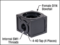
The back of the WFA2002 module has internal SM1 threads and four 4-40 taps for our 30 mm cage system.
- Internal SM1 (1.035"-40) Threads, Four 4-40 Taps for 30 mm
Cage Systems, and Female and Male D1N Dovetails - Magnetic Door Cover Holds Filter Cube in Optical Path
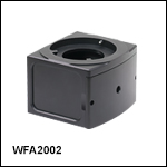
The WFA2002 Epi-Illuminator Module holds one filter cube and is the base module for the epi-illumination pathway of a Cerna® mini epi-fluorescence microscope. Additional modules are offered separately to support the addition of customer-built epi-illuminator modules. With a female D1N dovetail on top and a male D1N dovetail on the bottom, the WFA2002 is designed to mate with the epi-illumination arm of the microscope body, as well as with other epi-illuminator modules.
As shown in the image to the right, its optical input port has internal SM1 (1.035"-40) threads and four 4-40 taps for our 30 mm cage system. These mechanical interfaces enable Thorlabs' extensive selection of SM1 and 30 mm cage components to be used to build custom epi-illumination paths.
The module includes a magnetically secured cover that can be connected to a MDFM-MF2 filter cube, manufactured by Olympus (available above). Thorlabs' filter cubes provide reduced optic distortion and simpler optic mounting. The animation to the left shows the filter cube installation procedure. Extra covers, which the user can attach to the filter cubes to speed up filter cube exchange, are sold as Item # WFA2001C (available above). These filter cubes can be used to hold fluorescence filter sets, beamsplitters with crossed polarizers, or mirrors.
 Products Home




 Zoom
Zoom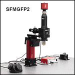
 Cerna Mini Microscopes