Autocorrelator for Femtosecond Lasers
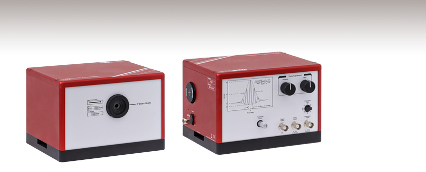
- Ultrafast Interferometric Autocorrelations for 650 - 1100 nm
- User-Adjustable Scan Range from 50 fs to 10 ps
- Integrated Iris and Alignment Target for Easy Setup
Front View
Back View
FSAC
Interferometric Autocorrelator

Please Wait
Click to Enlarge
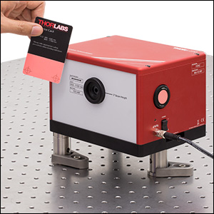
The iris and VRC2SM1 Alignment Target provide two reference points for alignment. Our VRC2 Viewing Card (sold separately) may be used to visualize the beam; it uses the same fluorescent material as the VRC2SM1 target.
Click to Enlarge
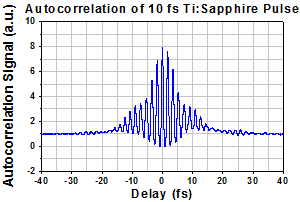
This interferometric autocorrelation was obtained using a Ti:sapphire laser. UMC10-15FS Precompensating Mirrors were used to chirp the beam prior to entering the autocorrelator.
Features
- Ultrafast Pulse Width Characterization for 650 - 1100 nm
- For Pulses from 40 fs to 1 ps, or Pulses Down to 15 fs with Precompensation
- Selectable Gain Up to 70 dB to Accommodate Large Range of Input Powers
- Interferogram Signal Output through BNC
- Scan Rate of 5 Hz
- Compact Footprint: 6.90" x 5.53" x 4.82"
Thorlabs' FSAC Interferometric Autocorrelator provides approximate pulse width measurements in the 650 - 1100 nm wavelength range. Well suited for diagnostics of femtosecond Ti:sapphire lasers, it consists primarily of a modified Michelson interferometer with a nonlinear detector at the output.
A BNC connector outputs the autocorrelation signal, which can be viewed on any oscilloscope with >1.5 MHz bandwidth. An example of the direct output from the FSAC is shown in the graph to the right. A photodiode amplifier with selectable gain from 0 dB to 70 dB provides compatibility with a large range of optical input powers, up to a maximum average power of 150 mW.
Intuitive, easy-to-reach controls on the outside of the enclosure allow the user to optimize the resolution and fringe contrast. The controls for the delay arm enable a full scan range of 50 fs to 10 ps (i.e., ±25 fs to ±5 ps), and a micrometer tunes the detector's position for maximum signal. Detailed usage recommendations and examples are available in the manual.
Setup Details
The FSAC autocorrelator is compatible with horizontally polarized input beams up to Ø4 mm (1/e2) and has a beam height of 3" (76.2 mm). A permanently installed SM1D12D Ring-Actuated Iris and an internally SM1-threaded side port provide two reference points for optical alignment. We include a VRC2SM1 Alignment Target and an SM1CP2 End Cap for this side port. To align, simply insert the FSAC into the beam path and rotate until the beam is centered on the target. A flip mount may be used to pick off the beam for regular diagnostics.
Two slots in the enclosure allow the autocorrelator to be locked down with the two included CL5 Table Clamps. In addition, three 1/4"-20 and three M6 x 1.0 tapped holes are located in the base, allowing the unit to be elevated to a desired height. Alternatively, the beam height and polarization may be adjusted by a suitable periscope, such as Thorlabs' RS99(/M) Periscope Assembly. In the image to the right, Thorlabs' Ø1" (Ø25.0 mm) Pedestal Posts have been used to set the FSAC at an optical height of 4.75". Recommended posts are given in the Specs tab.
It is important to note that the pulse width measured by the unit is obtained immediately before the photodiode. Thorlabs' Chirped Mirrors may be used to compensate for dispersion in the optical path. The group delay dispersion caused by the FSAC's internal optics is nominally 230 fs2 at 800 nm. Pulses as short as 40 fs FWHM can typically be measured without precompensation, but sub-40 fs FWHM pulses will require it. See the Precompensation tab for more details.
Click to Enlarge
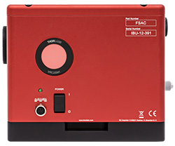
Side View
Each side has a centered slot that accepts
one of the included CL5 Table Clamps.
Click to Enlarge
Back View
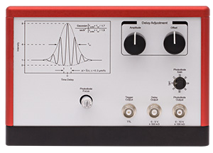
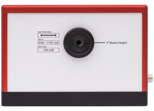
The back has controls for the scan range, photodiode
gain, and photodiode position, as well as the three
BNC outputs (see the Pin Diagrams tab).
| Item # | FSAC | |
|---|---|---|
| Input Wavelength Range | 650 - 1100 nm | |
| Input Pulse Duration | Without Precompensation | 40 fs to 1 ps (FWHM) |
| With Precompensationa | 15 fs to 1 ps (FWHM) | |
| Full Scan Range | 50 fs to 10 ps (±25 fs to ±5 ps) |
|
| Scan Rate | 5 Hz | |
| Noise-Equivalent Sensitivityb | 0.1 W2 at 800 nm for Ø1 mm Beam (1/e2) | |
| Input Polarization | Horizontal | |
| Input Beam Diameter | <Ø4 mm (1/e2) | |
| Input Repetition Ratec | >300 kHz | |
| Required Sampling Rate | >1.5 MHz for 10 ps Scan Range at 650 nm >150 kHz for 1 ps Scan Range at 650 nm |
|
| Internal Dispersion |
GDD | 230 fs2 at 800 nm (Nominal) |
| TOD | 345 fs3 at 800 nm (Nominal) | |
| Maximum Average Input Power | 150 mW | |
| Dimensions | 6.90" x 5.53" x 4.82" (175.3 mm x 140.4 mm x 122.4 mm) |
|
| Room Temperature Range | 17 to 25 °C | |
| Recommended Posts for Common Beam Heightsa | |
|---|---|
| 4.27" Beam Height | |
| Imperial Ø1" Posts | Three RS1P Pedestal Posts with Three RS028 Posts |
| Metric Ø25.0 mm Posts |
Three RS1P/M Pedestal Posts with Three RS7/M Posts |
| 4.75" Beam Height | |
| Imperial Ø1" Posts | Three RS1.5P Pedestal Posts with Three RS028 Posts |
| Metric Ø25.0 mm Posts | Three RS1.5P/M Pedestal Posts Three RS7/M Posts |
To reduce the effect of systematic error on pulse width measurements, we recommend precompensating for the dispersion caused by the FSAC's internal optics (e.g., the beamsplitter and focusing lens). Due to the significant and complex influence of dispersion on short-duration pulses, precompensation is most beneficial when measuring pulse widths from 40 fs down to 15 fs. For example, the systematic error on a Fourier-transform-limited 40 fs pulse is less than 10%, while the error reduces to less than 3% for pulses longer than 50 fs. The following describes a setup for providing precompensation using Thorlabs’ ultrafast optics.
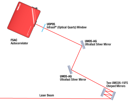
The precompensation setup is placed between the input laser beam and the FSAC, as shown in the diagram to the lower left. We simulated the effect of this setup on the measurement results of 15 fs pulses produced by a femtosecond laser. The dispersion precompensation optics comprised two UMC10-15FS chirped mirrors, between which the beam reflected five times, and a 1 mm thick UDP05 Infrasil® window. One reflection from Thorlabs' chirped mirrors provides -54 fs2 group delay dispersion (GDD) at 800 nm. Two UM05-AG silver mirrors were used to route the beam but did not contribute to the dispersion precompensation.
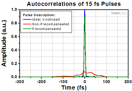
Simulated results from the setup described above are shown to the lower right. Used as a reference, the blue curve shows the calculated, ideal autocorrelation result for a 15 fs, unchirped, sech2-shaped, Fourier-transform-limited pulse. The red curve simulates the measurement results for a 15 fs pulse whose dispersion was not precompensated, and the green curve models the measurement results for a precompensated 15 fs pulse. Comparing the unchirped and precompensated pulse results demonstrates this precompensation setup achieves the desired effect of mitigating dispersion. The projected measurement error on the precompensated 15 fs pulse was calculated to be less than 10%.
Click to Enlarge
An illustration of a setup that uses chirped mirrors to compensate for the GDD caused by the internal optics of the FSAC. The graph to the right shows the results of a theoretical calculation of the effect of this setup on the autocorrelation measurement of a 15 fs pulse.
Click to Enlarge
Calculated Autocorrelation Results: Non-Precompensated and Precompensated Pulses Compared to an Ideal, Unchirped Pulse
Trigger Output
BNC Female
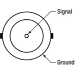
Outputs TTL Signal Synchronized with the 5 Hz Scan Rate
Delay Output
BNC Female

Outputs Signal Proportional to Position of Delay Arm
-5 V to +5 V; ≥100 kΩ
Photodiode Output
BNC Female

Outputs Autocorrelation Signal
0 V to +10 V; ≥100 kΩ
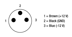
Cable on Included Power Supply
LUMBERG RSMV3-657/2M Male Connector
Sample MATLAB and Python Scripts
The download button below links to sample scripts that convert the interferometric autocorrelation from the FSAC into an intensity autocorrelation. Details are in Section 5.3 of the manual.
Click to Enlarge
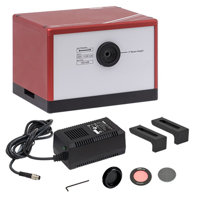
Items Included with FSAC (Region-Specific Power Cord Not Shown)
| Posted Comments: | |
Daniel Sandner
(posted 2024-03-26 10:16:49.367) Is it possible to measure the pulse width of a 1 kHz amplified Ti:Sa with this autocorrelator? cdolbashian
(posted 2024-03-29 12:10:05.0) Thank you for reaching out to us with this inquiry. This device is capable of characterizing pulses between 50 fs to 10 ps, with repetition rates >300kHz. That being said, these can be used with rep rates lower than 300kHz by using the autocorrelation signal to trigger an oscilloscope directly. I have contacted you to discuss this with you. Jake M
(posted 2022-06-17 19:07:18.813) Next, set the delay offset to approximately zero by
turning the offset knob all the way in one direction, and then turning 1.5 turns in the opposite direction so that the
indicator line is pointing up. The average voltage of the Delay Output should be near zero. While, I did this the pointer is turning down and delay output is not zero. Also what should be the integration time in oscilloscope? cdolbashian
(posted 2022-07-06 10:48:36.0) Thank you for contacting us with this issue Jake. I have reached out to you directly to troubleshoot this with you. For future troubleshooting inquiries, please contact us at Techsupport@thorlabs.com. sungtae park
(posted 2022-03-25 21:18:52.507) hi, i`m Mr,Park
I have a question.
If you look at the manual of the FSAC autocorrelator, in Interferometric Autocorrelation Trace, if it is a gaussian pulse, it is divided by 1.7, and if it is a sech square pulse, it is divided by 1.9. On the other hand, the Intensity Autocorrelation Trace says divide by 1.414 and divide by 1.543, respectively. I wonder what the difference between the two factors is and how to calculate it. Also can you give more detail how to calculate or convert Delay time axis? jdelia
(posted 2022-04-07 04:20:14.0) Thank you for contacting Thorlabs. The correction factors for autocorrelation traces are empirically derived. We have reached out to you directly to discuss resources on this, as well as clarify your inquiry about the time scale. John Yukich
(posted 2021-06-21 14:48:45.63) We wish to measure ultrafast pulses in the 10-15 fs range. The FSAC autocorrelator appears to be promising when used with pre-compensation. However, the webpage for the product has information in a couple of places stating that the minimum input pulse duration is 15 fs (see, for example, the "Specs" tab). A couple other places on the product webpage strongly suggest that measurements can be made down to 10 fs (see, for example, the sample autocorrelation data for a 10 fs pulse on the Overview tab).
We would greatly appreciate clarification on the minimum input pulse duration when pre-compensation is used. Thank you! YLohia
(posted 2021-07-12 08:05:43.0) Thank you for contacting Thorlabs. The only place I see where 10 fs is mentioned is the example trace from a Thorlabs Octavius laser. But without the original data, it's hard to say whether that trace is truly resolving the pulse. The FSAC will show a difference between 10 fs and 15 fs pulses (with proper dispersion compensation in both cases). The absolute accuracy of the measurement may not be good for 10 fs pulses though. Jay Winkler
(posted 2019-10-18 14:09:51.25) Can this autocorrelator be used on regeneratively amplified Ti:sapphire pulses at a repetition rate of 1 kHz if the power level is reduced to a specified level?
The specifications indicate that input repetition rates below 300 kHz are possible when using triggered acquisition.
What is meant by "triggered acquisition"?
Also, what is the maximum pulse energy that is safe to use? YLohia
(posted 2019-10-22 09:24:27.0) Thank you for contacting Thorlabs. In principle, the FSAC can be used at lower repetition rates by properly synchronizing (triggering) the acquisition with the laser. At repetition rates below spec the pulses don't "sample" the interferogram densely enough. We do not recommend it at such low repetition rates. It would require more translational repeatability than the FSAC is designed to provide. Also, the maximum pulse energy is fairly low, ~100 nJ. At 1 kHz and ~100 fs pulses, the product of peak power and average power is only 1E-4 W^2, which is well below the noise-equivalent sensitivity of 0.1 W^2. Reshma Mathew
(posted 2019-06-26 18:39:19.727) We have already purchased FSAC Autocorrelator. It's written in the power supply that the main voltage should match the line voltage switch. What does it mean? Can I use a power cord with 250 V and 6A? Will it damage the instrument? If I'm using such a power cord what will be the outcome? YLohia
(posted 2019-06-26 04:43:14.0) Hello, thank you for contacting Thorlabs. We include the LDS12B power supply with this item, which has a switchable AC input voltage (100, 120, or 230 VAC). We do not recommend using this with a 3rd party power supply with 250V & 6A output specs. ersen.beyatli
(posted 2019-03-02 08:17:34.957) What will be the price of FSAC when you arrange the scan range between 10fs-1ps? llamb
(posted 2019-03-07 04:11:59.0) Thank you for contacting Thorlabs. The minimum scan range is not a limit on the minimum measurable pulse duration, so the 50 fs scan range will provide plenty of resolution for short pulses like 10 fs. We have reached out to you directly for further discussion. ruben.criado
(posted 2017-10-26 11:21:53.173) Can you offer the autocorrelator at 1550 nm?
Thanks tfrisch
(posted 2017-10-31 04:23:43.0) Hello, thank you for contacting Thorlabs. I will reach out to you directly about the details of your source and our custom capabilities. |
 Products Home



 Femtosecond Autocorrelator