 Products Home / Technical Resources / Optical Elements Technical Publications / Beam Circularization Lab Fact
Beam Circularization Lab Fact

Please Wait

Click to Enlarge
Figure 1: The beam circularization systems were placed in the area of the experimental setup highlighted by the yellow rectangle.


Click to Enlarge
Figure 4: Spatial Filter System

Click to Enlarge
Figure 3: Anamorphic Prism Pair System

Click to Enlarge
Figure 2: Cylindrical Lens Pair System
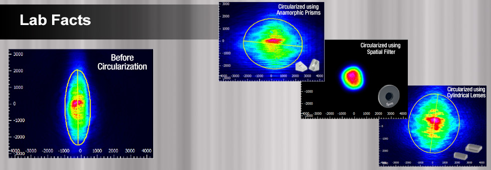
Comparison of Circularization Techniques for Elliptical Beams
Edge-emitting laser diodes emit elliptical beams as a consequence of the rectangular cross sections of their emission apertures. The component of the beam corresponding to the narrower dimension of the aperture has a greater divergence angle than the orthogonal beam component. As one component diverges more rapidly than the other, the beam shape is elliptical rather than circular.
Elliptical beam shapes can be undesirable, as the spot size of the focused beam is larger than if the beam were circular, and as larger spot sizes have lower irradiances (power per area). Techniques for circularizing an elliptical beam include those based on a pair of cylindrical lenses, an anamorphic prism pair, or a spatial filter. This work investigated all three approaches. The characteristics of the circularized beams were evaluated by performing M2 measurements, wavefront measurements, and measuring the transmitted power.
While it was demonstrated that each circularization technique improves the circularity of the elliptical input beam, each technique was shown to provide a different balance of circularization, beam quality, and transmitted power. The results of this work, which are documented in this Lab Fact, indicate that an application's specific requirements will determine which is the best circularization technique to choose.
Experimental Design and Setup
The experimental setup is shown in Figure 1. The elliptically-shaped, collimated beam of a temperature-stabilized 670 nm laser diode was input to each of our circularization systems shown in Figures 2 through 4. Collimation results in a low-divergence beam, but it does not affect the beam shape. Each system was based on one of the following:
- LJ1874L2-A and LJ1638L1-A Plano-Convex Convex Cylindrical Lenses (Figure 2)
- PS873-A Unmounted Anamorphic Prism Pair (Figure 3)
- Previous Generation KT310 Spatial Filter System with P5S Ø5 µm Pinhole (Figure 4)
The beam circularization systems, shown to the right, were placed, one at a time, in the vacant spot in the setup highlighted by the yellow rectangle. With this arrangement, it was possible to use the same experimental conditions when evaluating each circularization technique, which allowed the performance of each to be directly compared with the others. This experimental constraint required the use of fixturing that was not optimally compact, as well as the use of an unmounted anamorphic prism pair, instead of a more convenient mounted and pre-aligned anamorphic prism pair.
The characteristics of the beams output by the different circularization systems were evaluated by making measurements using a power meter, a wavefront sensor, and an M2 system. In the image of the experimental setup, all of these systems are shown on the right side of the table for illustrative purposes; they were used one at a time. The power meter was used to determine how much the beam circularization system attenuated the intensity of the input laser beam. The wavefront sensor provided a way to measure the aberrations of the output beam. The M2 system measurement describes the resemblance of the output beam to a Gaussian beam. Ideally, the circularization systems would not attenuate or aberrate the laser beam, and they would output a perfectly Gaussian beam.
Edge-emitting laser diodes also emit astigmatic beams, and it can be desirable to force the displaced focal points of the orthogonal beam components to overlap. Of the three circularization techniques investigated in this work, only the cylindrical lens pair can also compensate for astigmatism. The displacement between the focal spots of the orthogonal beam components were measured for each circularization technique. In the case of the cylindrical lens pair, their configuration was tuned to minimize the astigmatism in the laser beam. The astigmatism was reported as a normalized quantity.
Experimental Results
The experimental results are summarized in the following table, in which the green cells identify the best result in each category. Each circularization approach has its benefits. The best circularization technique for an application is determined by the system’s requirements for beam quality, transmitted optical power, and setup constraints.
Spatial filtering significantly improved the circularity and quality of the beam, but the beam had low transmitted power. The cylindrical lens pair provided a well-circularized beam and balanced circularization and beam quality with transmitted power. In addition, the cylindrical lens pair compensated for much of the beam's astigmatism. The circularity of the beam provided by the anamorphic prism pair compared well to that of the cylindrical lens pair. The beam output from the prisms had better M2 values and less wavefront error than the cylindrical lenses, but the transmitted power was lower.
| Method | Beam Intensity Profile | Circularitya | M2 Values | RMS Wavefront | Transmitted Power | Normalized Astigmatismb |
|---|---|---|---|---|---|---|
| Collimated Source Output (No Circularization Technique) |
 Click to Enlarge Scale in Microns |
0.36 | Y Axis: 1.63 |
0.17 | Not Applicable | 0.67 |
| Cylindrical Lens Pair |  Click to Enlarge Scale in Microns |
0.84 | X Axis: 1.90 Y Axis: 1.93 |
0.30 | 91% | 0.06 |
| Anamorphic Prism Pair |
 Click to Enlarge Scale in Microns |
0.82 | X Axis: 1.60 Y Axis: 1.46 |
0.16 | 80% | 1.25 |
| Spatial Filter |  Click to Enlarge Scale in Microns |
0.93 | X Axis: 1.05 Y Axis: 1.10 |
0.10 | 34% | 0.36 |
Components used in each circularization system were chosen to allow the same experimental setup be used for all experiments. This had the desired effect of allowing the results of all circularization techniques to be directly compared; however, optimizing the setup for a circularization technique could have improved its performance. The mounts used for the collimating lens and the anamorphic prism pair enabled easy manipulation and integration into this experimental system. It is possible that using smaller mounts would improve results by allowing the members of each pair to be more precisely positioned with respect to one another. In addition, using made-to-order cylindrical lenses with customized focal lengths may have improved the results of the cylindrical lens pair circularization system. All results may have been affected by the use of the beam profiler software algorithm to determine the beam radii used in the circularity calculation.
Additional Information
Some information describing selection and configuration procedures for several components used in this experimental work can be accessed by clicking the following hyperlinks:
| Posted Comments: | |
aruiz
(posted 2017-10-13 15:08:41.82) Great Lab Fact! tfrisch
(posted 2017-10-17 05:01:14.0) Thank you for the Feedback! If you have any questions or further ideas, we'd be glad to discuss them with you. Please reach out to us at TechSupport@Thorlabs.com |