 Products Home / Technical Resources / Fiber & Fiber Patch Cables Technical Publications / Multimode Fiber Beam Profiles Lab Facts
Multimode Fiber Beam Profiles Lab Facts

Please Wait

Thorlabs Lab Facts: Modifying Beam Profiles with Multimode Fibers
We present laboratory measurements demonstrating how the output beam profile from multimode fiber can be affected by the beam entry angle. In some applications, an alternative beam distribution such as a top hat or donut is desired instead of the inherent Gaussian distribution provided by typical optics. Here we investigated the effect of changing the input angle of a focused laser beam into a multimode fiber patch cable. Focusing the light normal to the fiber face produced a near-Gaussian output beam profile (Figure 1) and increasing the angle resulted in top hat- (Figure 2) and donut-shaped (Figure 3) beam profiles. These results demonstrate how multimode fibers can be used to change the shape of a beam profile.
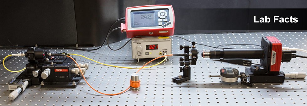
For our experiment, we used an M38L01 Ø200 µm, 0.39 NA, Step-Index Fiber Patch Cable (Bare Fiber Item # FT200EMT) as the test fiber into which we launched the focused laser beam. The input light was set incident at 0°, 11°, and 15° to the input face of the multimode fiber to create the initial, top hat, and donut profiles, respectively. Each time the angle was changed, the alignment of the input fiber was optimized while the output power was monitored with a power meter to ensure maximum coupling was achieved. Images were then acquired with a 9 second exposure and the shape of the beam profile was evaluated. Note that during the exposure, a 1500 grit diffuser was manually rotated between the coupling optics (before the fiber under test) to reduce the spatial coherence and create a clean output beam profile.

Assuming a ray tracing model, there are two general types of rays that propagate along a multimode fiber: (a) meridional rays, which pass through the central axis of the fiber after each reflection, and (b) skew rays, which never pass through the central axis of the fiber. The figures below illustrate the three basic ray propagation scenarios observed during the experiment. Figures 4 and 6 depict meridional and skew ray propagation through multimode fiber, respectively, and the associated theoretical beam distribution at the fiber output. As illustrated in Figure 6, skew rays propagate in a helical path along the fiber that is tangent to the inner caustic of the path with radius r. Figure 5 depicts the beam propagation and beam distribution from a combination of meridional and skew rays. By changing the input angle of the light launched into a multimode fiber, we were able to modify the proportion of light rays propagating as meridional rays vs. skew rays, and consequently, modify the output from a near-Gaussian distribution (primarily meridional rays, see Figure 1) to a top hat (mixture of meridional and skew rays, see Figure 2) to a donut (primarily skew rays, see Figure 3). The beam profiles shown in Figures 4 through 6 were obtained at a distance of 5 mm from the fiber end face. These results demonstrate the ability to use a standard multimode fiber patch cable as a relatively inexpensive method to modify an input Gaussian profile into a top hat and donut profile with minimal loss. For details on the experimental setup employed and these summarized results, please click here.
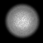
Figure 1. Near-Gaussian Beam Profile
Obtained at 0° Input Angle (Normal to Fiber Face)
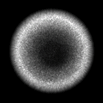
Figure 3. Donut Beam Profile
Obtained at 15° Input Angle
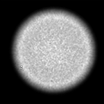
Figure 2. Top Hat Beam Profile
Obtained at 11° Input Angle


| Posted Comments: | |
| No Comments Posted |