 Products Home
高速光纤耦合探测器
- Sensitive to Wavelengths from 400 - 1700 nm
- Bandwidths from 1 to 5 GHz
- Rise Times as Short as 50 ps
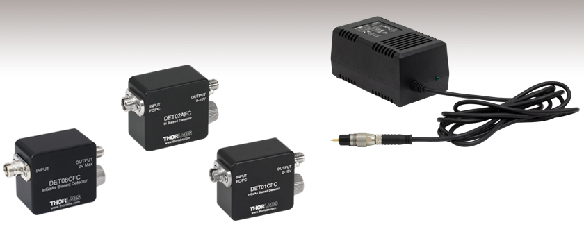
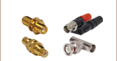
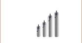
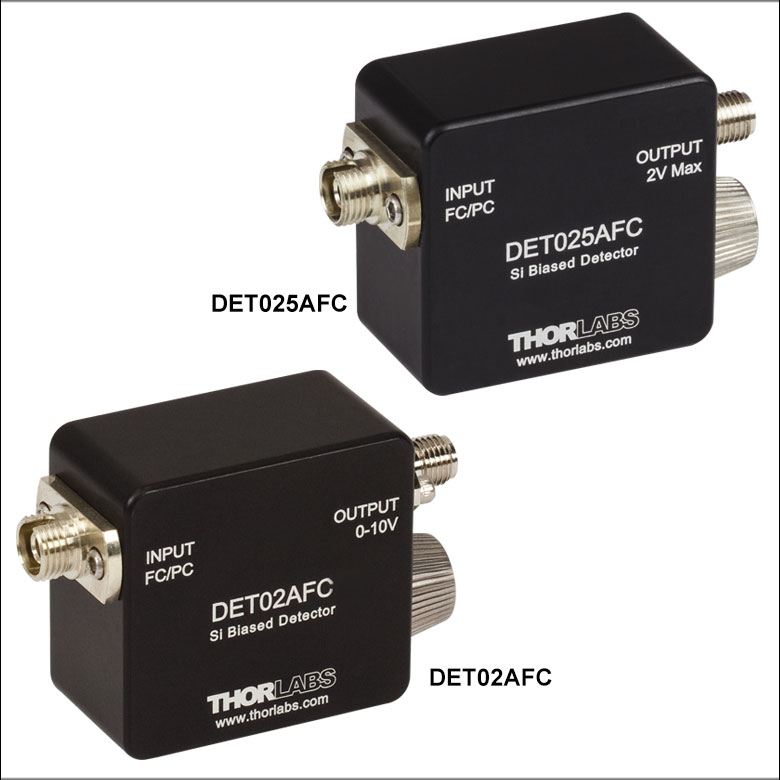
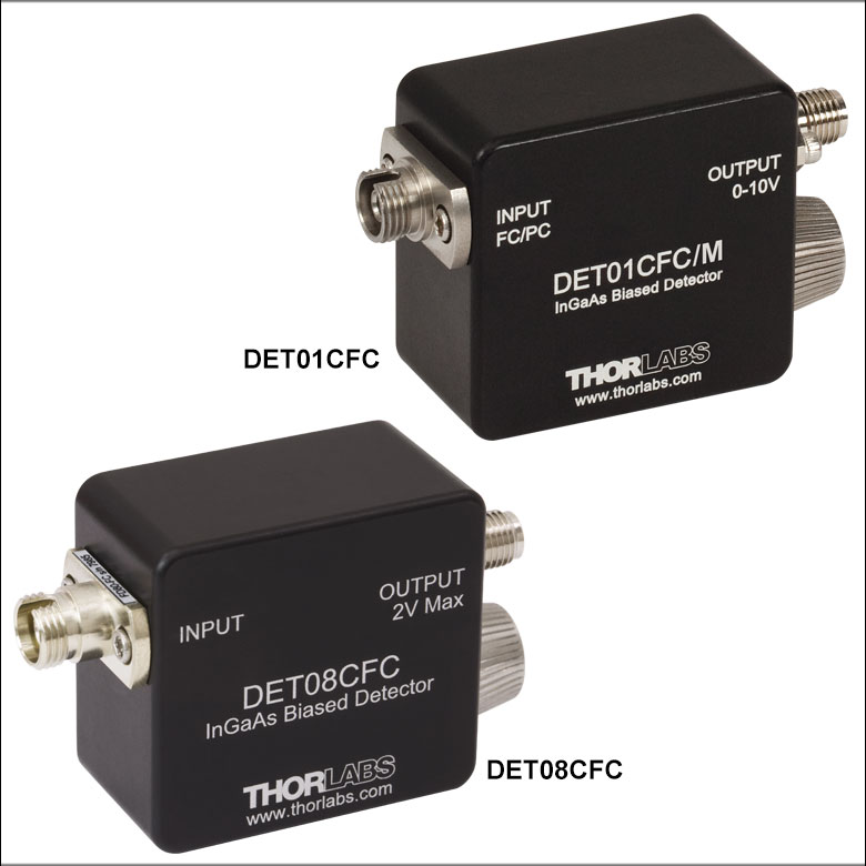
DET08CFC
DET02AFC
DET01CFC
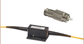
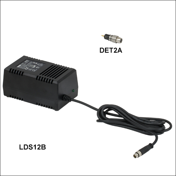
DET2B
Replaces the battery in our DET series detectors and includes the LDS12B power supply and DET2A power adapter, shown connected.


Please Wait
| Selection Guide for Fiber-Coupled Detectors | |||
|---|---|---|---|
| Wavelength | Element | Bandwidth | Model |
| 400 - 1100 nm | Si | 1 GHz | DET02AFC |
| 2 GHz | DET025AFC | ||
| 800 - 1700 nm | InGaAs | 1.2 GHz | DET01CFC |
| 800 - 1700 nm | 5 GHz (Max) | DET08CFC | |

特点
- 四种型号覆盖波长范围400-1700 nm
- 带宽从1到5 GHz
- 上升时间从50 ps到1 ns
- 连接到单模(SM)或多模(MM)光纤
- FC/PC光纤输入接头
- SMA输出接头
Thorlabs提供一系列光纤耦合,高速,高带宽探测器,可以连接FC/PC单模或多模光纤。这些探测器整体的灵敏范围从可见到近红外(400-1700 nm);请在右边的"Selection Guide"表格中查看每个探测器的准确光谱范围。本页所有探测器都有GHz信号带宽,和我们其它DET系列一样使用简单。这些探测器设计用于测试或测量应用,包括数据通信、模拟微波和一般的高速光子学。对于自由空间探测,Thorlabs提供高速自由空间探测器。我们还提供一系列内置偏压光电二极管,它们与光纤耦合光电探测器一样使用简单,但是工作速度较慢。我们的偏压光电探测器兼容台式光电二极管放大器和PMT跨阻放大器。
这些光纤耦合探测器反向偏置,内部有偏压电池,对入射光产生线性响应。为了保持高信号带宽,信号通过SMA接头输出。Thorlabs提供全系列电子转接件和电缆,包括SMA电缆和SMA转BNC转接件,方便在示波器或其它测量电子设备上监测信号。
我们基于硅的光纤耦合探测器用于400到1100 nm波长范围,带宽可选1 GHz (#DET02AFC)或2 GHz (#DET025AFC)。对于扩展到近红外的应用,可使用我们基于铟镓砷(InGaAs)的光纤耦合探测器,其探测范围从800到1700 nm,带宽可选1.2 GHz (#DET01CFC)或5 GHz (#DET08CFC)。对于高速信号监测,Thorlabs推荐使用50 Ω负载电阻。对于较低带宽应用,我们的可调终端连接头或固定终端连接头可以快速调节测量电压。
所有这些探测器包含一个可更换A23 12 VDC偏压电池,提供噪声极低的电源。该电池可用DET2B电源适配器套件(下面销售)代替,如果应用中只允许线电压噪声增加极小信号噪声,或者无法接受电池有限的寿命,这个套件将是理想选择。请注意,由于来自不同制造商的电池正极略有外形差异,Thorlabs建议只使用我们DET系列光电探测器中的Energizer®电池。
| Item # | DET02AFC | DET025AFC | DET01CFC | DET08CFC |
|---|---|---|---|---|
| Wavelength Range | 400 - 1100 nm | 400 - 1100 nm | 800 - 1700 nm | 800 - 1700 nm |
| Material | Si | Si | InGaAs | InGaAs |
| Bandwidth (-3 dB)a,b,c | 1 GHz | 2 GHz | 1.2 GHz | 5 GHz (Max) |
| Fiber Input | FC/PC | FC/PC | FC/PCd | FC/PC |
| Signal Output | SMA | SMA | SMA | SMA |
| Minimum Resistor Load | 50 Ω | 50 Ω | 50 Ω | 50 Ω |
| Maximum Peak Power | 18 mW | 18 mW | 18 mW | 100 mW |
| Saturation Power (CW) | - | - | 5.5 mW (1550 nm)b | - |
| Output Voltage | 0 to 3.3 V (50 Ω) 0 to 10 V (Hi-Z) | 2 V (Max)e | 0 to 1 V (50 Ω)f 0 to 10 V (Hi-Z) | 2 V (Max)e |
| Rise Time (tr)a,b,c | 1 ns @ 730 nm (Max) | 150 ps @ 653 nm, 20/80% (Typ.) | < 1 nsg @ 1310 nm | 70 ps @ 952 nm, 20/80% (Typ.) |
| Fall Time (tf)a,b,c | 1 ns @ 730 nm (Max) | 150 ps @ 653 nm, 80/20% (Typ.) | < 1 nsg @ 1310 nm | 110 ps @ 952 nm, 80/20% (Typ.) |
| Bias Voltage | 12 V | |||
| Dark Current | 126 pAh | 35 pAa,h | 0.235 nAa,h | 1.5 nAa,h |
| NEP (Maximum) | 9.5 x 10⁻¹⁵ W/√Hz (@ 730 nm) | 9.29 x 10⁻¹⁵ W/√Hz (@ 730 nm) | 4.5 x 10⁻¹⁵ W/√Hz (@ 1550 nm) | 2 x 10-15 W/√Hz (@ 1550 nm) |
| Junction Capacitance | 1.73 pF (Max) | 1.73 pF (Max) | 2.4 pF (Typical) | 0.3 pF |
| Photodiode Element | FDS02 | FDS02 | FGA01FC | - |


信号输出
SMA母头
0 - 10 V w/ 50 Ω
电池寿命
在使用电池供电的光电探测器时,了解电池的寿命和它对探测器工作的影响是很重要的。光电探测器是一种电流输出器件,其输出电流正比于入射到探测器的光强。大部分用户用一个终端负载电阻把该电流转换成电压。电阻值与电路增益大致相等。对于非常高速的探测器,比如本页销售的探测器,使用50 Ω终端电阻匹配标准同轴电缆的阻抗非常重要,从而减少电缆反射并提高整体信号的性能和完整性。大部分高带宽示波器都配备了这种终端电阻。
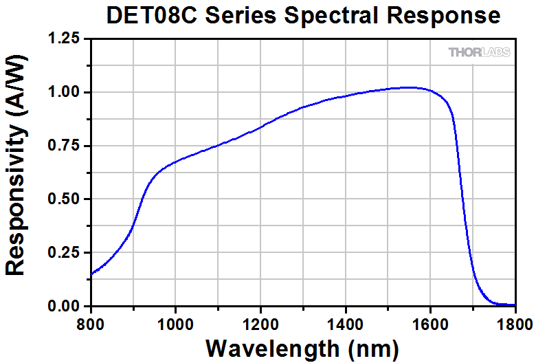
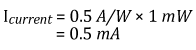
电池的使用寿命与探测器使用的电流直接相关。大部分电池制造商以mAh(毫安时)定义电池寿命。例如,DET08CFC探测器包含的电池是40 mAh。这表示以1.0 mA电流能够工作40小时。下面的例子说明了如何根据用途确定该电池的寿命。
在此例中,我们将平均功率为1 mW、波长为780 nm的光源入射到探测器上。根据响应曲线,在此波长下偏压探测器的响应为0.5 A/W。光电流可按照下式计算:
电池标称寿命为40 mAh,所以电池将持续工作时间为:
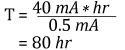
或连续使用3.3天。如果入射光的平均功率减小为10 µW,同一个电池将能够连续不断地工作约333天。当使用推荐的50 Ω终端负载时,0.5 mA光电流根据下式转换为的电压:
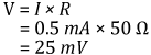
如果入射功率水平降到10 µW,输出电压将变为0.25 mV。对于一些测量设备,这个信号水平可能太低,这时就需要折衷考虑电池寿命和测量精度。
当使用电池供电的偏压光电探测器时,需要使用尽可能低的光强,也要注意要求的最低电压水平。同时需要记住的是,电池在接近使用寿命时并不会立即停止产生电流。不过电池电压将降低,施加在光电二极管两端的电势将减小。这将增加探测器的响应时间并降低探测器带宽。因此,请确保探测器在指定参数下工作时电池能够提供足够的电压(见探测器手册中的故障检修章节)。可以用万用表来检查电压。
提高电池寿命的另一个建议是移开或减弱入射在探测面上的光。没有光照时,光电探测器也会产生和光电探测器暗电流成正比的电流,但是这个电流要小很多。比如,DET08CFC的暗电流小于1.5 nA。
对于DET系列光电探测器持续被相对较高功率的光源照明的应用,或者不能接受替换电池时,我们提供包含电源转接件和电源的DET2B套件(下方出售)。这个方法的缺点在于线电压中的噪声将叠加到输出信号上,可能引入更大的测量不确定性。
光电二极管教程
工作原理
结光电二极管是一种基本器件,功能类似于普通的信号二极管,但在结半导体的耗尽区吸收光时,会产生光电流。光电二极管是一种快速、高线性度器件,根据应用具有高量子效率,可用于多种应用。
根据入射光正确确定期望的输出电流水平和响应度很有必要。图1为一个结光电二极管模型,它由基本独立元件组成,这样便于直观地了解光电二极管的主要特性,并更好地掌握Thorlabs光电二极管的工作过程。
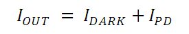
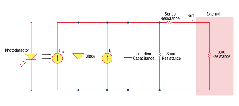
图1:光电二极管模型
光电二极管相关术语
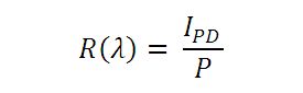
响应度
光电二极管的响应度可以定义为给定波长下,产生的光电流(IPD)和入射光功率(P)之比:
工作模式(光导模式和光伏模式)
光电二极管具有两种工作模式:光导模式(反向偏置)或光伏模式(零偏置)。工作模式的选择取决于应用中的速度要求和可容许的暗电流(漏电流)大小。
光导模式
光导模式时,光电二极管被施加外部反向偏压,这是我们DET系列探测器的基础。电路中测得的电流代表器件接受到的光照;测量的输出电流与输入光功率成正比。施加反向偏压使得耗尽区的宽度增大,从而使响应度增加,结电容变小,并产生相当线性的响应度。在这些条件下工作容易产生较大的暗电流,但根据光电二极管的材料可限制其大小。(注: 我们的DET器件都是反向偏置的,不能在正向偏压下工作。)
光伏模式
光伏模式时,光电二极管为零偏置。器件的电流流动受到限制,形成电压。这种工作模式利用了光伏效应,它是太阳能电池的基础。当在光伏模式下工作时,暗电流可保持最小。
暗电流
暗电流是光电二极管有偏压时的漏电流。在光导模式工作时,容易出现更高的暗电流,并与温度直接相关。温度每升高10 °C,暗电流几乎增加一倍,并且温度每增加6 °C,并联电阻增大一倍。显然,施加较大的偏压会降低结电容,但也会增加当前暗电流的大小。
当前暗电流也受光电二极管材料和有源区尺寸的影响。与具有高暗电流的锗器件相比,硅器件的暗电流通常较小。下表给出了几种光电二极管材料及它们的相关暗电流、速度、响应波段和成本。
| Material | Dark Current | Speed | Spectral Range | Cost |
|---|---|---|---|---|
| Silicon (Si) | Low | High Speed | Visible to NIR | Low |
| Germanium (Ge) | High | Low Speed | NIR | Low |
| Gallium Phosphide (GaP) | Low | High Speed | UV to Visible | Moderate |
| Indium Gallium Arsenide (InGaAs) | Low | High Speed | NIR | Moderate |
| Indium Arsenide Antimonide (InAsSb) | High | Low Speed | NIR to MIR | High |
| Extended Range Indium Gallium Arsenide (InGaAs) | High | High Speed | NIR | High |
| Mercury Cadmium Telluride (MCT, HgCdTe) | High | Low Speed | NIR to MIR | High |
结电容
结电容(Cj)是光电二极管的一个重要性能,对光电二极管的带宽和响应有很大影响。需要注意的是,结区面积大的二极管结体积也越大,同时具有较大的充电电容。在反向偏压应用中,结的耗尽区宽度增加,可有效地减小结电容,并增大响应速度。
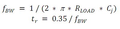
带宽和响应
负载电阻和光电二极管的电容共同限制带宽。要得到最佳的频率响应,应将50 Ω的终端与50 Ω的同轴电缆一起使用。带宽(fBW)和上升时间响应(tr)可以近似用结电容(Cj)和负载电阻(Rload)表示:
噪声等效功率
噪声等效功率(NEP)是信噪比等于1时产生的RMS信号电压。NEP非常有用,因为它决定了探测器探测弱光的能力。通常,NEP随着探测器的有源区而增大,并由下式表示:

其中,S/N是信噪比,Δf是噪声带宽,入射能量的单位是W/cm2。关于NEP的更多信息,请查看Thorlabs的噪声等效功率白皮书。
终端电阻
使用负载电阻将光电流转换为电压(VOUT)以便在示波器上显示:
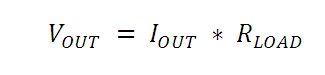
根据光电二极管的类型,负载电阻会影响响应速度。为达到最大带宽,我们建议使用50 Ω同轴电缆,并在另一端使用50 Ω终端电阻。因其与电缆的本征阻抗相匹配,可最小化谐振。不考虑带宽时,可增大负载电阻(Rload),从而增大给定光功率下的光电压。终端不匹配时,同轴电缆的长度对响应的影响很大,所以我们建议电缆越短越好。
并联电阻
并联电阻表示零偏压下光电二极管的结电阻。理想的光电二极管具有无限大的并联电阻,但实际值可能从十欧姆到几千兆欧不等,这与光电二极管的材料有关。例如,InGaAs探测器的并联电阻在10 MΩ量级,而Ge探测器的并联电阻在kΩ量级。这会严重影响光电二极管的噪声电流。然而,在大部分应用中,大电阻的影响很小,因而可以忽略。
串联电阻
串联电阻是半导体材料的电阻,这种小电阻通常可以忽略。串联电阻来自于光电二极管的触点和线接头,通常用来确定光电二极管在零偏压下的线性度。
通用工作电路
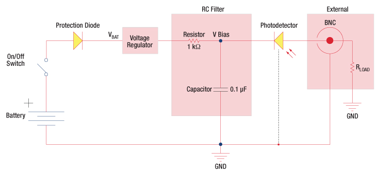
图2:反向偏压电路(DET系列探测器)
DET系列探测器具有如上所示的电路模型。探测器通过反向偏置以对输入光产生线性响应。光电流的大小基于入射光和波长,通过在输出端加一个负载电阻就可以在示波器查看。RC滤波电路的作用是滤掉输入电源的高频噪声,这些噪声可能会导致输出噪声。
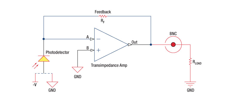
图3:带放大的探测器电路
也可以用光电探测器加放大器来实现高增益。用户可以选择是否在光伏或光导模式下工作。使用这个有源电路有几个优势:
- 光伏模式:由于运算放大器A点电势和B点电势相等,因而光电二极管两端的电势差为零伏。这样消除了暗电流的可能。
- 光导模式:光电二极管反向偏置,从而增大了带宽并降低了结电容。探测器的增益与反馈元件(Rf)有关。探测器的带宽可用下式计算:
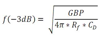
其中GBP是放大器增益带宽积,CD是结电容和放大器电容之和。
斩波频率的影响
光导体信号将保持不变,直到时间常数响应极限为止。许多探测器(包括PbS、PbSe、HgCdTe(MCT)和InAsSb探测器具有1/f的典型噪声频谱(即,噪声随着斩波频率增大而减小),这对低频时的时间常数具有较大影响。
探测器在较低斩波频率下会表现出较低响应度。频率响应和探测率对于下式可最大化
![]()
| Posted Comments: | |
Binod Joshi
(posted 2024-09-04 15:37:40.947) Hi,
Would it be possible to obtain the raw data (or better yet, the expression for an empirical function) for the typical pulse response of DET08CFC? I have been trying to model the "Typical Pulse Response" curve on pp 12 of its User Guide, but haven't had much success. Previously, I was told by Thorlabs support that such data was not available at that moment.
Thanks. ksosnowski
(posted 2024-09-05 01:41:17.0) Hello Binod, and thank you for sharing this feedback with us. We are working to update this webpage to include a download for an excel format of this pulse response along with the plots on the Graphs tab above. I have reached out directly to discuss this further. user
(posted 2024-03-29 21:44:50.07) 最近使用附近实验室购买的这款DET08CFC/M测量脉冲光脉宽时出现了严重的拖尾,实际30ns的脉宽拖尾将近500微秒,您有对此相关的解释嘛? ksosnowski
(posted 2024-03-29 09:53:32.0) Hello, thanks for reaching out to Thorlabs. The most common issue users face with this detector is with the measurement load impedance. 50 Ohm is required as a load to get the full bandwidth of this fast detector. Some oscilloscopes with higher input impedance like 1MOhm will decrease the bandwidth unless a 50 Ohm termination resistor is used in parallel at the input. Our VT2 and FT500 around common to use for this purpose. This load directly effects the RC time constant of the photodiode system resulting in 20000x higher rise time for a 1MOhm load versus 50 Ohm. The load in Ohms also serves as the gain in V/A in this setup so 50 Ohm is expected to result in a smaller amplitude response than higher impedance measurements. If a combination of higher bandwidth and gain are needed, then a transimpedance amplifier may be necessary to readout a very small optic signal as a significant voltage. A member from your local tech support team has reached out directly to discuss this application in further detail. 子康 王
(posted 2024-03-14 12:04:48.97) 请问,这个型号的小信号的探测性能怎么样,其指标是什么 ksosnowski
(posted 2024-03-14 11:46:11.0) Hello, thanks for reaching out to Thorlabs. DET01CFC's noise floor is defined by our NEP value 4.5 x 10⁻¹⁵ W/sqrt(Hz) which is a density of RMS noise in the frequency spectrum and given at the 1:1 signal to noise ratio (SNR) point. This NEP is given near peak responsivity, so non-peak wavelengths will have proportionally higher noise floor. One must multiply the NEP value by the square root of bandwidth to obtain the optical power level of the noise floor for the system. If using the full bandwidth of DET01CFC at peak wavelength the noise floor is approximately 0.16 nW. As this is only the 1:1 SNR point, most practical setups will require a higher SNR which must be determined by the user for the application. A member from your local tech support team has reached out to discuss your application in further detail. allan bereczki
(posted 2023-08-22 07:36:19.533) Hello. does thorlabs sell replacement phtotodiode for DET08CFC? ksosnowski
(posted 2023-08-22 11:37:35.0) Hello Allan, thanks for reaching out to Thorlabs. The photodiode used in DET08x and DET02x series are not ones we sell separately. DET025x uses our FDS02 diode and DET01x uses our FGA01FC. We are however able to replace the photodiode inside these detectors if the device is damaged. I have reached out directly to discuss your application in further detail. Yazan Lampert
(posted 2023-08-11 18:31:32.743) Dear all,
we are interested in purchasing DET08CFC from you and I would like to know more about the maximum peak power you provide. Is the value 100 mW the damage threshold or is it the saturation power of the diode?
Best regards,
Yazan Lampert ksosnowski
(posted 2023-08-11 04:20:00.0) Thanks for reaching out to Thorlabs. DET08x series' 100mW max power is given by the OEM relative to the safe photocurrent limit on the microwire bonds to the sensor. Exceeding this input can generate excessive heat and damage, resulting in failure of the photodiode as an open circuit with zero current response. This is a thermal effect however the microwires will also have a very short thermal time constant so spiking past this is not recommended. This is separate from optical saturation which occurs after the output voltage passes the applied bias level. Due to the 50 Ohm load required for high bandwidth on these devices, saturation typically occurs well after the photocurrent limit. Saturation Power will depend on the load resistance and wavelength response/photocurrent which yield an output at the fixed saturation i.e. bias voltage. Saturation leads to accelerated diode aging and can cause a permanent increase in device dark current. These effects can occur relative to how far past saturation the device is operated and for how long. As saturation is where the output linearity suffers, it is not generally considered useful to operate at or past this point.
We further recommend limiting the output swing on these devices to 2V max amplitude. Typical scopes or amplifiers may see slew limited performance in a combined large signal regime with high speed operation though this does largely depend on the measurement device used on the DET. cdolbashian
(posted 2023-07-24 08:54:07.0) Thanks for reaching out to Thorlabs. The noise floor characteristics are described by the Noise Equivalent Power (NEP) spec of the detector. NEP is defined as the optical power required for 1:1 SNR in a system, considering the peak response wavelength, and normalized to 1Hz. As electrical noise occurs across a frequency spectrum, we have measured the entire bandwidth of the detector and integrated noise across this and normalized for the NEP rating. This allows you to consider various system bandwidths with a single rating. For better linearity you would want higher SNR. If you use a lowpass filter on the output of this, that could further restrict the total bandwidth, reducing the noise spectrum sampled and total noise seen. So having excessive bandwidth beyond the actual experiment will only introduce extra noise from that higher frequency part of the noise spectrum. I recommend viewing the Photodiode Tutorial tab on this page which links to our NEP whitepaper with further details on this topic. Madhav Gupta
(posted 2023-07-20 21:25:40.093) Hello
I am currently using DET025AC/M as a fluorescence detector in an optical microscope. I am using AMP100 (https://www.thorlabs.com/thorproduct.cfm?partnumber=AMP100) as a transimpedance amplifier, and trying to measure the output voltage using a standard oscilloscope or an arduino. Unfortunately, the voltage reading is quite low so I am trying to debug what the problem is.
I had a few questions:
1) Is the AMP100 compatible with DET025AC/M?
2) On the DET025AC/M webpage, the PMT transimpedance amplifier is recommended (https://www.thorlabs.com/newgrouppage9.cfm?objectgroup_id=8862). What is the main different between PMT and the AMP100? Do I need to purchase the PMT for my experiments?
Please let me know. If you think the AMP100 should work, I'll try and see if there is any alignment error in my microscope.
Also, please let me know if you suggest any other solutions on how to read out the photodiode voltage for my experiment.
Thanks a lot,
Madhav cdolbashian
(posted 2023-07-25 08:54:07.0) Thank you for reaching out to us with this inquiry. Depending on the signal you are detecting, and your instrumentation, you might be exceeding the bandwidth of the amplifier, thus seeing little-to-no amplification. The AMP100 has a maximum 1kHz bandwidth, while the PMT amplifier (TIA60) has a 3dB bandwidth of ~60MHz. I have contacted you directly to troubleshoot this issue. For future troubleshooting help, please contact techsupport@thorlabs.com as that is our dedicated support channel! user
(posted 2023-04-27 15:44:00.937) hello,
We are using DET08CFC/M photodetector to measure the rise time of a 100 ns pulse. What we expect is a perfect square pulse, but we are observing a pulse with rise/ fall time of around 50 ns (which is not expected). Can you please comment on this? (We had ensured that the battery is supplying sufficient volts)
thanks. ksosnowski
(posted 2023-05-25 11:02:14.0) Hello, thanks for reaching out to Thorlabs. The two major things that directly effect DET bandwidth are the load resistance and the diode capacitance. The battery provides the bias source which keeps capacitance low and within the designed range. Together these form an RC lowpass filter which defines the cutoff frequency for the bandwidth. I would recommend to check termination resistance, and see if reducing the input power changes the distortion. Though full saturation doesn't occur until output reaches the 10V bias level, we do recommend limiting the output on DET08 series to 2V max to prevent pulse distortion. Daniela Schubert
(posted 2023-03-16 10:14:23.76) Dear Thorlabs-Team,
which fiber-coupled photodetector do you recommend for the measurement of fs-pulses (e.g. Pav = 10mW, frep = 100MHz, Tp = 100 fs)?
Best regards ksosnowski
(posted 2023-03-17 06:35:10.0) Hello Daniela, thanks for reaching out to Thorlabs. For ultrafast pulses like this I recommend considering our FPD series detectors from Menlo Systems. FPD510-FC-VIS is one fiber coupled version with silicon photodiode. These are quite sensitive devices and would require attenuation to avoid damaging the sensor. The saturation and damage thresholds for the FPD series are given in the Specs table on our website. The DET series on this specific page are not optimized for ultrafast pulses and will see effective attenuation due to the high bandwidth of pulses in the femtosecond regime as standard photodiodes act like a lowpass filter up to their bandwidth. I have reached out directly to discuss this application further. subba rao y v
(posted 2022-10-07 13:08:32.88) Dear Sir,
We purchased the detector DET08CFC/M and also a DET2B power supply. In the description it is mentioned peak power is 100mW. Now I want to connect the CW laser. Can I connect the CW laser power of 20mW. Kindly reply the optical input power range for DET08CFC/M.
Regards,
Y. V. Subba rao. ksosnowski
(posted 2022-10-10 05:33:22.0) Thanks for reaching out to Thorlabs. We do not have an exact CW limit for the power, as this can vary with wavelength and load, but it is recommended to keep operation below saturation, and with DET08CFC we recommend further limiting the output to <2V for best bandwidth. In most cases, 20mW will saturate the sensor which can lead to early sensor degradation. There is a photocurrent limit of 0.5mA due to the DET08CFC sensor's small internal wires, this thermal effect will limit the continuous photocurrent the unit can deliver but under peak conditions it can briefly sustain higher currents. With 50 Ohm loads, this photocurrent limit will occur before saturation for the design wavelength range. Nikita Kikilich
(posted 2022-07-14 06:28:26.907) Hi. My photodetector is behaving strangely. I detect pulses with a length of 100 ns, and I see a signal in the form of a saw (very long fall time). With another photodetector from another company, everything is OK. Could you tell if the photodetector is possibly damaged? What could have led to this and what went wrong in it? Due to what did his fall time increase physically? ksosnowski
(posted 2022-07-28 04:35:07.0) Thanks for contacting Thorlabs. General technical issues like this are best direct to techsupport@thorlabs.com. Regarding these issues, I recommend to check the battery voltage is above 9V and replace if needed. Make sure to use the shortest BNC cable with no extra attachments. A higher system capacitance and load resistance will negatively effect bandwidth and rise time directly. A low battery will drop the bias voltage and raise capacitance as well. Reducing input optical power can also check if saturation is effecting the measurement speed. I have reached out directly to discuss this issue further. user
(posted 2022-05-09 16:24:20.757) Can the DET02AFC and DET025AFC be used with an FC/APC patch cable (similar to how the DET01CFC and DET08CFC can be used with FC/APC)? Thank you for the help. ksosnowski
(posted 2022-05-13 01:42:48.0) Thanks for reaching out to Thorlabs. While we have not tested the DET02AFC and DET025AFC directly with FC/APC connectors, we do not generally expect any issues with this application. It is designed to couple FC/PC cores 70um or smaller, so at this upper limit there would be some inherent loss due to the angled output, but at smaller core sizes it should have minimal effect on performance. David Conlon
(posted 2022-02-14 16:59:03.467) We have the detector DET08CFC/M and also a DET2B power supply for feeding it. Now we want to pack our system but the package of the DET2B is very big for our package. So I would ask, can we use another 12V-250mA power supply for our DET08?
What can we do for its three pin power input socket? cdolbashian
(posted 2022-02-18 04:57:52.0) Thank you for reaching out to us David. The DET2B (power supply), when used with the DET2A (power adapter) and any of the DET* detectors, will function not as a power supply, but as a reverse bias module, taking the place of the 12V battery which is already included in the DET* units. Pinout information including voltage and current requirements can be found in the spec sheet for the DET2B: https://www.thorlabs.com/_sd.cfm?fileName=TTN148688-S01.pdf&partNumber=DET2B. I have reached out to you directly to discuss your application further.
For future tech support inquiries, please feel free to reach out to us at Techsupport@thorlabs.com user
(posted 2021-08-11 10:15:42.013) I am trying to understand the difference between DET025AFC and DET02AFC. Why is the lower bandwidth option slightly cheaper? What really limits the bandwidth? The junction capacitance is the same but the bandwidths differ by 2x and the rise times by 7x (contradicting the information in the manuals). Do both feature DC-coupled outputs? cdolbashian
(posted 2021-10-15 04:39:02.0) Thank you for reaching out to us at Thorlabs! These devices have a slightly different implementation of the circuit design internally, allowing for a larger output voltage while maintaining a high bandwidth. We note in our photodiode tutorial here(https://www.thorlabs.com/newgrouppage9.cfm?objectgroup_id=10741&tabname=bias%20voltage). As the output voltage increases, the effective voltage decreases. Based on our testing, we restrict the recommended output to 2V to maintain the specced response speed. Both devices are DC coupled. I have contacted you directly to discuss this further. user
(posted 2021-08-05 11:44:25.427) Do you have a SPICE model for the detector or a diode model that closely matches the characteristics of this device? YLohia
(posted 2021-08-27 02:49:51.0) Hello, thank you for contacting Thorlabs. Unfortunately, we do not have SPICE models or any other programmatic models for our photodiodes. Daniela Manoel
(posted 2021-05-31 10:25:38.253) If I send the light into this connector using no fiber optics, directly through free space, and manage to make a measurement, can I trust the detector response? Is there any big problem in operating the DET08FCPC like this? Thanks a lot. Regards YLohia
(posted 2021-06-15 03:10:02.0) Thank you for contacting Thorlabs. These fiber-coupled detectors have a ball lens which will take the diverging light from a fiber and will refocus it on to the detector surface. Using a free space source into the fiber-coupled input will likely cause an overfilling of the detector surface, yielding an increased rise/fall time on the order of micro seconds. Properly filling (not overfilling) the detector area will yield optimal response time. user
(posted 2021-04-26 04:53:25.65) Hi, I am looking at the specs of the DET08CFC photodetector but I cannot find the sensitivity (dBm). Could you provide this value or some estimate at 1550 nm? Thank you. cdolbashian
(posted 2021-08-31 04:12:32.0) Thank you for contacting us at Thorlabs. After discussing this with you directly, I found that you were interested in the minimum detectable optical power @1550nm. This can be calculated by following the methods outlined in our NEP white paper: https://www.thorlabs.com/images/TabImages/Noise_Equivalent_Power_White_Paper.pdf Maged Esmail
(posted 2021-03-23 05:35:38.333) Hi
We have DET01CFC device in our lab. The problem is that we are not able to connect any fiber to this device. It is very strange. It looks it uses a different FC connector. Could you tell us what is this type of connectors and what is the suitable fiber connect that matches it?
Thank you asundararaj
(posted 2021-03-29 02:02:21.0) Thank you for contacting Thorlabs. The DET01CFC has an FC/PC Fiber Input Connector and an SMA connector for the Electrical Signal Output. I have contacted you for further assistance. Surjit kaman
(posted 2021-02-13 17:20:19.823) Hii,
I want it to connect the DET08CFC, to a lock-in amplifier/Oscilloscope. The scope has a 50-ohm impedance. Should I still use 50 ohm for the scope?
What is the detector output? asundararaj
(posted 2021-02-15 03:08:22.0) Thank you for contacting Thorlabs. The output of a DET08CFC is the photocurrent, and if the oscilloscope already has a 50 Ω impedance then you do not need to have an additional 50 Ω termination. In this case, the output will be read across the impedance of the scope. Nordine Hendaoui
(posted 2020-12-29 08:37:35.187) Hello,
for using the DET01CFC, We have to purchase only the DET2B as power supply. This last is powerd by 220 v?
Thanks asundararaj
(posted 2020-12-29 04:52:40.0) Thank you for contacting Thorlabs. The DET2B includes the DET power adapter and the LDS12B power supply. The power supply has a switchable AC input voltage (100, 120, or 230 VAC), which will have to be switched to 230 VAC setting. A region-specific power cord is also shipped with the LDS12B power supply based on your location. liangze pan
(posted 2020-05-18 13:10:42.937) Hey,would you mind provide the frequency response curve of the photo detector of DET025AFC/M YLohia
(posted 2020-05-27 09:39:50.0) Hello, thank you for contacting Thorlabs. Unfortunately, we do not have a frequency response curve for this detector at the moment. liangze pan
(posted 2020-05-07 15:50:29.337) Hey,would you mind to provide the frequency response curve of the photo detector of DET025AFC/M. YLohia
(posted 2020-06-09 11:16:31.0) Hello, thank you for contacting Thorlabs. I have reached out to you directly to discuss your request. Jo Wanki
(posted 2019-11-07 04:13:27.263) I have a question. I am using DET08CFC / M. I'm wondering where to fit the laser to the DET08CFC / M INPUT part when measuring the pulse width.
Currently we inspect a laser set to a 12 nsec pulse width value. If we measure from the periphery to the center of the DET08CFC / M INPUT part, a value ranging from 10.8 nsec to 13 nsec is measured.
So we wonder. Please let me know if there is any information on whether the laser should be placed in the center of the DET08CFC / M INPUT site, whether it should be around or measured. YLohia
(posted 2019-11-07 10:32:51.0) Thank you for contacting Thorlabs. For the maximum bandwidth, the spot should be <50% of the active area (ideally in the geometrical center of the photodiode). The edges of the detector tend to have a slower response time, and overfilling the detector will give a convolution of rise times across the active area. Daniel Fernando Borrero
(posted 2019-10-25 11:24:28.08) I would like to know if this detector can be used to do correlation counting experiments, I need to connect the detectors to a TCSPC module, will they work? asundararaj
(posted 2019-10-29 03:05:31.0) Thank you for contacting Thorlabs. The DET025AFC is not sensitive enough to count photons. You can find our Single Photon Counters here: https://www.thorlabs.com/newgrouppage9.cfm?objectgroup_id=5255 Philip Skochinski
(posted 2019-10-21 14:05:44.74) What is the voltage output for a given optical input? I need to be able to calculate the electrical power (in 50 Ohms) for a specific optical input power. asundararaj
(posted 2019-10-21 04:59:14.0) Thank you for contacting Thorlabs. The output voltage from the detector can be estimated from the optical power incident using following equation:
Voltage measured (V) = Optical Input (W) * Responsivity (A/W) * Terminating Resistance (Ohms)
You can find the typical responsivity in the Graphs tab of this page or in the detector Manual. user
(posted 2019-09-05 04:10:22.24) Hello,
For the DET01CFC(/M), you have specfified a Saturation Power (CW) = 5.5 mW (1550 nm) for a 50 Ohms load
But for the DET08CFC/M, it is specified a Maximum Output Voltage VOUT=2 V (Max). Could you provide me with the optical power producing this 2V or what is the Saturation Power (CW) in mW for this detector? I aks this because I have a fast modulation (GHz) on top of CW light level.
Thanks! asundararaj
(posted 2019-09-06 04:19:13.0) Thank you for contacting Thorlabs. The saturation threshold of a detector depends on many factors such as load resistance value, beam profile and size, modulation characteristics, wavelength, bias voltage, diode temperature, etc. For more details regarding this, please see our "Lab Fact" on photodiode saturation limits here: https://www.thorlabs.com/images/TabImages/Photodetector_Lab.pdf.
We do not have an official spec on the saturation of the DET08CFC. I will reach out to you directly to discuss this further. jwchew33
(posted 2018-07-09 01:53:12.373) Greeting, I have a problem on DET08CFC/M. When I input square waveform at frequencies range from 1kHz to 1MHz into the photodetector, the output results did not show square waveform as expected. However, by using the same setup using PDA50B-EC detector (input 1kHz-400kHz), square waveform were observed. The pulse width used was 10us. I'm not sure what to do next. Any help? Thanks. YLohia
(posted 2018-07-25 08:43:15.0) Hello, thank you for contacting Thorlabs. What load impedance are you using on your oscilloscope? You should be using 50 Ohms for ideal performance. Is the battery for the DET fully charged? I will reach out to you directly to troubleshoot this further. dlee103
(posted 2018-03-16 15:55:18.063) What is the saturation threshold in mW? YLohia
(posted 2018-04-19 03:39:43.0) Hello, thank you for contacting Thorlabs. The saturation threshold of a detector depends on many factors such as load resistance value, beam profile and size, modulation characteristics, wavelength, bias voltage, diode temperature, etc. For more details regarding this, please see our "Lab Fact" on photodiode saturation limits here: https://www.thorlabs.com/images/TabImages/Photodetector_Lab.pdf. The DET025AFC is designed for pulsed/modulated light sources so the saturation limit can depend heavily on modulation characteristics. For example, a few milliwatts (1 to 2 mW for peak wavelength) is a safe theoretical estimate for CW sources, while we spec 18mW of peak power for pulsed sources. There is a resistor in series as a part of an RC circuit within the detector packaging, which limits the CW saturation power. user
(posted 2016-11-04 16:39:22.64) The manual linked for DET01CFC says that the battery should be installed negative side in. The diagram on the detector and the spring inside the battery cap suggest the opposite is true. tfrisch
(posted 2016-11-04 04:50:19.0) Hello, thank you for contacting Thorlabs. Section 4.11 of the manual calls for the battery to be inserted into the cap with the negative terminal inside the cap (in contact with the coil spring). When the cap is threaded back onto the housing, that will put the positive of the battery in the housing. mitch
(posted 2016-03-22 09:10:48.767) Hi, would it be possible for me to buy the metal fibre attachment that is attached to the input of these devices, by itself? I have purchased four of the free space, window versions (along with several tens of thousand dollars of other stuff) but I would like to try attach a fibre and I don't want to buy another set (the budget is now mostly spent!). Thanks besembeson
(posted 2016-03-24 10:23:31.0) Response from Bweh at Thorlabs USA: The sensor for the fiber versions comes coupled to the fiber connector. I will contact you if this is still suitable for your application. songtaodu
(posted 2016-01-21 17:08:49.07) When I used DET08CFC to detect output light of a fiber laser,wavelength of this laser is 1550nm and output is CW, the output voltage of DET08CFC kept at 13.2V while the laser power varied from 0.5mW to 3mW.
When I turn off the laser, the output voltage of DET08CFC is zero.
Can you tell me why this happened? Thanks! jlow
(posted 2016-01-22 01:28:18.0) Response from Jeremy at Thorlabs: It seems like you are basically measuring the voltage of the battery. The DET08CFC output s current signal. To use that with an oscilloscope or a voltmeter, you will need a load resistor or a terminator in series and measure the voltage drop across the resistor /terminator instead. An example of the terminator would be the T4119 terminator. rmillett
(posted 2014-09-03 11:28:46.62) Could a calibrated transfer curve be available for these detectors? In particular a response curve that could be calibrated out from low (kHz) frequencies to 5GHz? jlow
(posted 2014-09-04 04:06:29.0) Response from Jeremy at Thorlabs: We will look into measuring this and will e-mail you directly on our findings. kmurari
(posted 2013-05-03 16:17:01.92) My DET02AFC appears to be AC coupled although the manual says the SMA output is DC coupled. I have checked the battery, it is at >12 V. Can you please confirm if the unit is indeed DC coupled?
Thanks! jlow
(posted 2013-05-03 18:07:00.0) Response from Jeremy at Thorlabs: The DET02AFC should be DC-coupled. I will contact you directly to troubleshoot this. jlow
(posted 2012-12-21 10:39:00.0) Response from Jeremy at Thorlabs: The detector's active area has a diameter of Ø120µm. There's also a Ø1.5mm ball lens in front of the detector. The output from a SMF28 fiber should be fully captured by the detector. For MM fiber, we recommend using a fiber with at most 50µm core size (around 0.2 NA). neil.troy
(posted 2012-12-06 00:01:17.15) For the fiber coupled devices will a single mode fiber's (say SMF-28 for example) divergence be fully captured by the detector? What about a multi-mode fiber? ie. what is the distance from the output face of the fiber to the detector surface as well as what are the detector's active areas? tcohen
(posted 2012-04-05 15:19:00.0) Response from Tim at Thorlabs to jzheng: Thank you for your feedback! The typical rise time of the DET02 will still be ~50ps at your wavelength. jzheng
(posted 2012-03-26 01:56:40.0) For the wavelength 1053nm, is the rise time of the DET02 (Si) still be 50ps? or will be longer? thank you. jjurado
(posted 2011-02-08 18:27:00.0) Response from Javier at Thorlabs to last poster: Thank you very much for submitting your request. For the high bandwidth detectors, a switch is not included since it significantly impairs the BW performance of the detector. In general, the DET’s draw very little current when no light is applied to the sensor. A battery will last on the order of years without a light signal applied. For these detectors, it is recommended that the light source is removed from the sensor when not being used. This will preserve the battery life. user
(posted 2011-02-08 17:00:05.0) It looks free space DET series has a battery switch. Do I have to remove a battery out of a box of the fiber input DETs every time? klee
(posted 2009-10-05 14:39:34.0) A response from Ken at Thorlabs to dinglu81: Thank you for pointing out the discrepancy. It should be 10^-15. dinglu81
(posted 2009-10-02 05:41:25.0) the NEP of this detector is 10^-15 in the specs but 10^-14 in the catalog. Which one is correct? Greg
(posted 2009-02-18 15:37:16.0) A response from Greg at Thorlabs to remi.riviere: Thank you for your interest in Thorlabs products. Please see the e-mail I sent you and reply to it with the detector you are looking for more information on. I will then check what other information we have available on it. remi.riviere
(posted 2009-02-18 05:01:42.0) Please provide a gain curve as well as the dynamic range of this detector. acable
(posted 2008-08-31 12:59:35.0) Please add NEP data. |
下表列出了Thorlabs的光电二极管、光电导和热释电探测器。同一行的产品型号包含相同的探测元件。

 放大
放大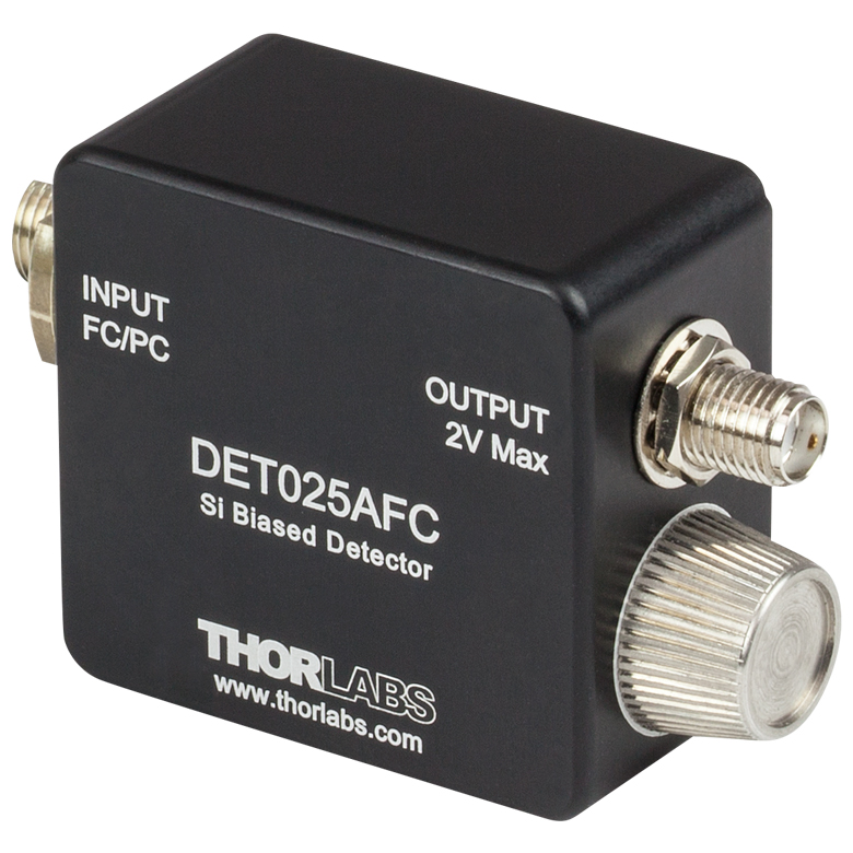
- DET02AFC:带宽1 GHz,上升时间1 ns
- DET025AFC:带宽2 GHz,上升时间150 ps
DET02AFC(/M)和DET025AFC(/M)高速光纤耦合探测器设计用于400到1100 nm光谱范围。它们使用我们的FDS02硅光电二极管探测器,带宽分别是1 GHz和2 GHz。8-32螺纹安装孔(公制为M4)兼容我们的Ø1/2英寸接杆。
| Item # | Wavelength | Detector | Bandwidth | Max Peak Power | Rise Time | Fall Time |
|---|---|---|---|---|---|---|
| DET02AFC | 400 - 1100 nm | Si | 1 GHz | 18 mW | 1 ns (Max) | 1 ns (Max) |
| DET025AFC | 400 - 1100 nm | Si | 2 GHz | 18 mW | 150 ps (Typ.) | 150 ps (Typ.) |

 放大
放大
A23是Thorlabs DET光电探测器更换用的碱性电池。对于电池有限寿命不能接受的情况,我们也提供AC电源适配器;更多信息,请见下方。关于电池使用寿命的信息,请查看上方电池寿命标签。

 放大
放大- DET2A:电源适配器,用于DET系列探测器
- LDS12B:±12 VDC电源
- DET2B:包含DET2A和LDS12B的套件
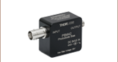
DET2A电源适配器
DET2A电源适配器用于我们的DET系列探测器。该适配器可以直接替换A23电池和装有弹簧的盖子,从而通过LDS12B电源(单独出售)直接工作。DET2A也兼容PDA-C-72电源线,方便用户自定义连接。请注意,DET2A和PDA-C-72给DET系列探测器供电时,只需要使用褐色((+12 V)和黑色(接地)两个引脚。
LDS12B电源
LDS12B是一个±12 VDC的稳压电源,集成功能包括:用于短路和过载保护的电流限制;带LED指示灯的开关;可切换的交流输入电压(100、120或230 VAC)。LDS12B发货时会根据所在地区附带一根符合当地标准的电源线。
DET2B电源适配器套件
DET2B电源适配器套件包括DET2A电源适配器和LDS12B电源。该套件可以替换我们DET系列探测器中的电池。使用DET2B时,只需用其中的DET2A适配器替换电池和装有弹簧的盖子,然后将LDS12B电源的三针插头插入适配器中,再将适配器拧到探测器上即可。具体过程见右边视频。

 放大
放大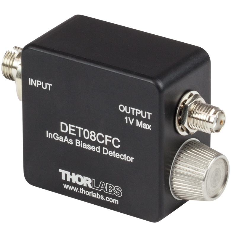
- DET01CFC:带宽1.2 GHz,上升时间< 1 ns
- DET08CFC:带宽5 GHz,上升时间70 ps
DET01CFC(/M)设计用于800到1700 nm光谱范围。它使用我们的FGA01FC铟镓砷光电二极管探测元件,带宽1.2GHz。它具有一个FC/PC输入接头,但从我们的测试来看,使用FC/APC光纤跳线没有可测量的性能差异。8-32螺纹安装孔(公制为M4)兼容我们的Ø1/2英寸接杆。
DET08CFC(/M)设计用于800到1700 nm光谱范围。它使用InGaAs探测元件,带宽5GHz。它具有一个FC/PC输入接头,但从我们的测试来看,使用FC/APC光纤跳线没有可测量的性能差异。8-32螺纹安装孔(公制为M4)兼容我们的Ø1/2英寸接杆。
| Item # | Wavelength | Detector | Bandwidth | Max Peak Power | Rise Time | Fall Time |
|---|---|---|---|---|---|---|
| DET01CFC | 800 - 1700 nm | InGaAs | 1.2 GHz | 18 mW | < 1 nsa | < 1 nsa |
| DET08CFC | 800 - 1700 nm | InGaAs | 5 GHz (Max) | 100 mW | 70 ps (Typ.) | 110 ps (Typ.) |