Ø1.5" Post Construction Accessories
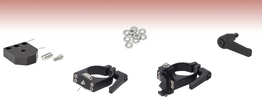
- Ideal for Securing Optomechanics to Our Ø1.5" Stainless Steel Posts
- Rigid Construction Provides Stability for Sensitive Alignment Assemblies
#8 (M4) Counterbore
1/4"-20 (M6) Tap
Rotating 8-32 (M4) Mounting Stud
MA1
Post Mounting Adapter
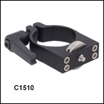
C1510
Compact Post Clamp
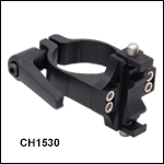
CH1530
30 mm Cage System Adapter
SD1
Adapter Ring
C15QR
Quick-Release Handle

Please Wait
Click to Enlarge
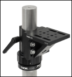
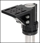
C1515 Mounting Bracket with C15QR Quick-Release Handle Placed Above a PSHA Adjustable Height Collar
| Ø1.5" Post Accessories |
|---|
| Construction Accessories |
| V-Mounts |
| Mounting Plates |
| Brackets / Platforms |
| Mirror Mounts |
These post mounting adapters provide direct compatibility between virtually all of our Optomechanics and our Ø1.5" posts.
Compact Post Clamp
The C1510(/M) Compact Post Clamp allows optic mounts with 8-32 (M4) tapped mounting holes to be attached to a Ø1.5" post. The angle of the optic mount can be adjusted easily using the knurled knob.
Slip-On Post Clamps
Our slip-on post clamps can be used for mounting 1/4"-20 (M6) components to our Ø1.5" posts. When the SD1 counterbore adapter ring is being used, 8-32 (M4) components can also be mounted.
Cage Clamp Mounts
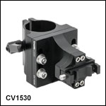
Our CH1530(/M), CH1560(/M), and CV1530(/M) Cage Clamp Mounts allow 30 mm or 60 mm cage assemblies to be securely attached in a horizontal or vertical direction to our Ø1.5" posts using a quick-connect mechanism.
Post Mounting Adapters
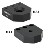
Our post mounting adapters function as mounting platforms for Ø1.5" posts. They are offered with several configurations of 1/4"-20 (M6) and 8-32 (M4) tapped holes and counterbores.
Quick-Release Handle
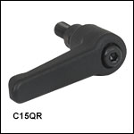
A quick-release handle is also available that allows for a simple and reliable way of securing clamps to a post. The handle is compatible with any clamp that uses a 1/4"-20 (M6) locking screw. The 2.03" (51.4 mm) long handle contains a 1/4"-20 (M6) threaded stud that engages the part by simply rotating the handle. It is included on all of the items below except for the C1498(/M) Slip-on Clamp and the post mounting adapters.
Adjustable Height Collar
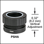
The PSHA(/M) Adjustable Height Collar allows for fine height adjustment of post-mounted components. It is compatible with our Ø1.5" posts and offers up to 0.32" of vertical adjustment.
| Posted Comments: | |
ludoangot
(posted 2017-04-10 11:19:47.743) What are the recommended and maximum torques that can be applied on the C1510(/M)? I am planning to add a 12.7mm post on the mounting stud and an c-mount camera to have a throw of about 130mm from the 1.5" post. Or can you recommend another solution to have an at least 120mm throw from a post (or rail)? tfrisch
(posted 2017-04-27 03:01:16.0) Hello, thank you for contacting Thorlabs. I will contact you directly about solutions for mounting off of a post. You may also want to consider optical rails. apalmentieri
(posted 2010-01-20 14:42:35.0) A response from Adam at Thorlabs to n.kunst: The measurements in the pdf of the MA4/M are correct. Unfortunately, this product would not fit on the T12XYZ/M. We could make a custom version that would align two of the tapped holes to the spacing of the T12XYZ/M for compatible mounting. Another option, if you do not need 12.7mm travel, would be to use the MS3. The MS3 contains two tapped M4 holes that will line up with the tapped holes on the MA4/M. My only concern would be the amount of equipment you would be mounting to the MA4/M. The vertical load capcity of the MS3 is 2.5lbs and the horizontal load capcity is 7lbs. n.kunst
(posted 2010-01-20 10:06:08.0) Are the measurements in the pdf of MA4/M correct metric?
Does it fit on the t12xyz/m ?
plsease respond to my email: n.kunst@science.ru.nl
thanks,
Nick nkaddy
(posted 2008-06-18 09:38:46.0) Superb! A great company policy - Im very pleased to hear that! Tyler
(posted 2008-06-04 11:10:04.0) A response from Tyler at Thorlabs to nkaddy: Although we dont have a formal procedure, both the idea and the customers name are passed onto the design engineer. If the idea results in a new product or a redesigned product we often involve the customer in the testing of the prototype(s) and the customer is usually given the prototype version that is put into production. We chose to make this forum public because it was our hope that people like you would share their experiences with the science community. So even if the C1500 isnt redesigned, your idea may help other members of the science community improve their experimental setup. Thorlabs is not only interested in improving our product line, but in finding ways for us and our customers to contribute to the knowledge base of the scientific community. nkaddy
(posted 2008-06-04 08:57:56.0) To Tyler: Perhaps then you should have an incentives scheme, where if the feedback is useful you offer to make one of the items for the person suggesting it? Tyler
(posted 2008-05-22 10:18:20.0) A response from Tyler at Thorlabs to nkaddy: Thank you for sharing your solution with us and all the other users of this part. The information you provided has been passed on to the design engineers. Please continue to use this feedback forum to let us know about your experiences in the lab. We will use the information to try and make products that make your lab more productive. nkaddy
(posted 2008-05-21 11:38:37.0) Hi acable, we ended up tapping an M2 thread into the side of the C1500 and added a spacer to the M4 thread projecting from the front so that the opto-mech can be tightend with the wheel still able to move freely. Once in position, an M2 screw in the newly tapped thread locks the wheel. I also tried thrust washers, they were OKish but not as effective and definately not set and forget. acable
(posted 2008-04-05 09:41:47.0) The way i use the C1500 actually allows a piece of opto-mech with a tapped hole (#8-32 or M4) to be rotated to any orientation. I snug the mount down to the C1500 but leave it just loose enough to rotate, once i have the orientation i want i then use a 5/64" hex wrench inserted into one of the side holes on the locking wheel to full tighten the device. While this takes two hands, the result is a very stable mounting arrangement that allows the mating optical mount to be secured at an angle. nkaddy
(posted 2008-04-05 08:12:31.0) Hi Laurie, Please email me for the details of the changes we made to the product to make it considerably more flexible. Laurie
(posted 2008-03-25 10:29:14.0) Response from Laurie at Thorlabs to nkaddy: Thank you for your suggestion on how to improve this product! We always enjoy receiving such input from the users of our products. I have passed your suggestion on to our mechanics design team so that they can consider it. Thanks again for taking the time to contact us! nkaddy
(posted 2008-03-25 10:15:24.0) I like the idea of the C1500 but was disappointed to find that the wheel doesnt rotate once the mount is fixed into place. If you had a mount that would fix first and then could be rotated with the four holes actually providing locking screws I think youd have a better product. |

Click for Details
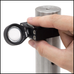
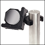
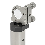
LMR1 Lens Mount Mounted to Ø1.5" Post Using C1510 Compact Clamp
- Attach Optic Mounts with 8-32 (M4) Taps to Ø1.5" P-Series Posts
- Knurled Knob for Coarse Angle Adjustment
- Four Holes on the Knob for Extra Leverage when Tightening (Click on the Image to the Right for Details)
- Includes Quick-Release Handle for Easy Mounting to Ø1.5" Posts
The C1510(/M) Compact Post Clamp allows optic mounts with 8-32 (M4) tapped holes to be attached to a Ø1.5" post. Each compact post clamp includes a C15QR(/M) Quick-Release Handle for mounting to a Ø1.5" post; replacement quick-release handles can be purchased separately below. For low-profile applications, the handle can be removed and replaced with a 1/4"-20 (M6) cap screw at least 1/2" (12 mm) long.
Clicking on the image to the right displays a sequence of three images illustrating the mounting procedure using an LMR1 lens mount. The angle of the optic mount can be set in place (see image 1) while the knurled knob is used to thread the device onto the C1510 (see image 2). For final tightening, a 5/64" (2 mm) hex key or ball driver can be inserted into the four holes provided on the knob (see image 3). This enables the user to exert additional torque in the final tightening stage.

- Mount 1/4"-20 (M6) or 8-32 (M4) Components onto our Ø1.5" P-Series Posts
- Lock to Post with Non-Marring Brass Locking Screw
- Two 8-32 (M4) Tapped Holes are Provided for Optic Mounts with #8 (M4) Counterbored Holes
- 1/4" Counterbore for Mounting Components with 1/4"-20 (M6) Threading
- Use the SD1 Adapter in the 1/4" Counterbore to Mount Components with 8-32 (M4) Threading
The image to the right shows a Ø2" PF20-03-P01 silver mirror mounted in a Ø2" KS2 mirror mount, which is connected to the C1498 post clamp using the 8-32 (M4) threading.

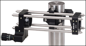
Click to Enlarge 30 mm Cage System Mounted on a Ø1.5" Post Using a CH1530 Clamp
- Securely Mount 30 mm or 60 mm Cage Systems to our Ø1.5" Posts
- Quick-Connect Mechanism for Fast Drop-In/Drop-Out of Cage Assemblies using Ø6 mm Cage Rods
- Cage Clamping Mechanism Activated by 3/16" (5 mm) Hex Cap Screw
- Includes Quick-Release Handle for Easy Mounting to Ø1.5" Posts
The CH1530(/M) and CH1560(/M) Cage Clamps allow 30 mm or 60 mm cage systems, respectively, to be mounted horizontally to our Ø1.5" Posts. The quick-connect mechanism allows for drop-in/drop-out mounting of a cage segment; to secure the cage segment, tighten the hex cap screw on the cage clamping mechanism using a 9/64" (3 mm) hex key or balldriver. Each cage clamp includes a C15QR(/M) Quick-Release Handle for mounting to a Ø1.5" post; additional quick-release handles can be purchased separately below. For low-profile applications, the handle can be removed and replaced with a 1/4"-20 (M6) cap screw at least 1/2" (12 mm) long.
The application to the right shows the CH1530 supporting a cage system composed of 4 ER6 cage rods, an SM1ZA Z-Axis Translation Mount, and a CP33T cage plate. This system can be used as a telescope to expand or contract the beam diameter using lenses of appropriate focal length placed in the Z-axis mount and cage plate.

- Mount 30 mm Cage Systems to Our Ø1.5" Posts
- Can Be Oriented to Mount Cage Systems Vertically or Horizontally
- Quick-Connect Mechanism for Fast Drop-In/Drop-Out of Cage Assemblies
- 15 lb (6.8 kg) Load Capacity
The CV1530(/M) Cage Clamp allows a 30 mm cage system to be mounted vertically to our Ø1.5" Posts. The quick-connect mechanism allows for drop-in/drop-out mounting of a cage segment; to secure the cage segment, tighten the cap screw on the cage clamping mechanism using a 9/64" (3 mm) hex key or balldriver. Each cage clamp includes a C15QR(/M) Quick-Release Handle for mounting to a Ø1.5" post; additional quick-release handles can be purchased separately below. For low-profile applications, the handle can be removed and replaced with a 1/4"-20 (M6) cap screw at least 1/2" (12 mm) long.
The vertical cage clamp can be converted to a horizontal cage clamp. To do so, unscrew the four cap screws on either side of the cage clamps using a 9/64" (3 mm) balldriver or hex key, turn the front plate 90°, and replace the cap screws.
Custom CV1530(/M) Clamp Mounts can be ordered for 16 and 60 mm cage system compatibility. Please contact Tech Support for more information.

- Can be used as a Mounting Platform to Connect a Wide Range of our Optic Mounts and Translation Stages to our Ø1.5" P-Series Posts
- Offers Several Configurations of 1/4"-20 (M6) and 8-32 (M4) Tapped Holes and Counterbores
The application to the right shows a Ø1" POLARIS-K1E ultra-stable mirror mount attached to an MA4 Post Mounting Adapter using 8-32 (M4) threading. The 1/4" clearance on the MA4 adapter is used to connect to the 1/4"-20 threading of the Ø1.5" post.


Click for Details
Left: C15QR Quick-Release Handle Being Attached to the C1511 Post Mounting Clamp
Right: Pull Back to Rotate the Position of the Handle
- Quick-Release Handle for Fast and Repeated Positioning of Post Clamps
- Compatible with Ø1" (Ø25.0 mm) or Ø1.5" Post Clamps that Incorporate a 1/4"-20 (M6) Clamping Screw
- Provides More Control and Feel when Locking and Unlocking a Clamp
- Handle can be Rotated Without Actuating the Locking Screw
- 1/4"-20 (M6) Threads
The C15QR(/M) Quick-Release Handle provides a simple and reliable way of securing a flexure-based Ø1" (Ø25.0 mm) or Ø1.5" post clamp. In many cases a cap screw is used to lock a flexure-based clamp in place on a post, which requires a balldriver for adjustments. Depending on the mounted load, using a balldriver can be difficult, or even unsafe. This quick-release handle mitigates this problem by allowing the clamp to be hand-tightened, ensuring better control over the amount of torque applied to tighten or loosen the clamp. This also decreases the amount of time needed for basic setup and alignment by eliminating the need for additional balldrivers and allowing for a quick way to secure a clamp.
Easily installed by replacing the 1/4"-20 (M6) locking screw in a post clamp, the 2.03" (51.4 mm) long handle contains a 1/4"-20 (M6) threaded stud that engages a part by rotating the handle. Once the handle is tightened to secure a clamp to a post, the internal ratchet-type mechanism allows for the handle's rotational position to be adjusted without actuating the mounting stud. Simply pull the handle outwards to disengage it from the mounting stud, as shown in the image to the right, then rotate it to a more convenient position. This feature ensures that the handle will always be accessible to the user.

- 0.025" (0.64 mm) Travel per Revolution
- 0.32" (8.2 mm) Vertical Adjustment Range
The PSHA(/M) Adjustable Height Ø1.5" Post Collar offers a convenient height adjustment for post mounted hardware. An easy-to-access actuator ring allows fine height adjustment at 0.025" (0.64 mm) per revolution. This collar also allows components to be freely rotated without changing height.
To use, slip the collar over a Ø1.5" post and hold at the desired height. Tighten the 1/4"-20 (M6) cap screw to secure the collar's position on the post via the flexure clamp. Place an optomechanic around the post on top of the collar and twist the actuator ring to adjust the component's height. The height can be locked by tightening the 8-32 setscrew with a 5/64" (2 mm) hex. The nylon ring on top of the collar prevents marring while adjusting the height.
 Products Home


 Zoom
Zoom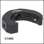
 Ø1.5" Post Accessories