Modular Multi-Port Integrating Spheres

- Ø100 mm Integrating Sphere of Durable, Highly Reflective Sintered Optical PTFE
- Modular Design Offered as Two Pre-Configured Versions or Custom Configurations
- 3 or 4 Modular Faces for Single-Port, Dual-Port, or Cuvette Holder Port Inserts
- Up to Eight Ø5 mm Ports
4P4
Reflection Measurement
Integrating Sphere
Back View
Front View
Interchangeable Port Inserts for Modular Faces
4P10
4P11
4P12
4P13
Application Idea
Integrating Sphere with
4P20 Cuvette Holder Port Insert

Please Wait

Click to Enlarge
4P4 Sphere Major Design Features
| Compatible Mounted Photodiodes | ||
|---|---|---|
| Sensor Type | Wavelength Range | Photodiodes |
| Si | 200 - 1100 nm | SM1PD2A |
| Si | 350 - 1100 nm | SM1PD1A SM1PD1B |
| InGaAs | 800 - 1700 nm | SM05PD5Aa |
| Ge | 800 - 1800 nm | SM05PD6Aa |
Features
- Ø100 mm Inner Diameter in Modular, Cuboctahedral Housing
- Pre-Configured and Custom-Configured Integrating Spheres
- 3 or 4 Modular Faces with Interchangeable Port Inserts
- Standard Port Inserts: Ø14 mm Dual Ports, Ø1" Port, Ø2" Port, or Port Plug
- Cuvette Holder Port Insert for 12.5 mm x 12.5 mm Cuvettes
- Up to Eight 8 Ø5 mm Ports with SM1 Threading
- Directly Connect Our SM1 Photodiodes (See Table to the Lower Right)
- Mount Fiber-Coupled Light Sources using SM1 Fiber Adapters
- Durable, White, Highly Reflective Sphere Material
- Operating Range: 250 - 2500 nm (Unless Limited by the Detector)
- Universal 8-32 / M4 x 0.7 Tap on Side Panels for Rail System (Included with Stock Items) or Mounting to Ø1" Posts
Thorlabs' Modular Integrating Spheres each provide a durable, highly reflective surface to optimally diffuse light. The sphere is constructed inside a cuboctahedral (fourteen-sided) housing that can be configured for a wide variety of applications. Each of the eight triangular faces can support a Ø5 mm port with SM1 internal threads, enabling easy mounting of our mounted photodiodes or fiber-coupled components such as LEDs or spectrometers (SM1 adapters may be needed). Either three or four of the square faces can be configured with inserts selected by the user as described in the Modularity section below. The two faces that are not modular provide a universal 8-32 / M4 x 0.7 tapped hole, allowing mounting to the 25 mm rail system stand (included with stock items) or a Ø1" post. These integrating spheres are available from stock as one of two pre-set configurations or ordered as a custom configuration using the tool below.
The spheres are manufactured from PTFE-based bulk material that has high reflectance in the 250 - 2500 nm wavelength range (see Specs tab) and is resistant to heat, humidity, and high levels of radiation. This reflective surface is designed to have specific roughness and diffusive reflection properties and should not be cleaned using solvents, as this could damage the inner surface. We only recommend using compressed air for cleaning the inner surfaces of the integrating spheres.
Integrating spheres enable high sensitivity measurements of optical signals in a variety of setups. An integrating sphere causes the incoming radiation to undergo multiple reflections over the sphere surface, which diffuses and depolarizes the light beam. This makes it the ideal instrument for many applications such as laser power, flux, reflectance and radiance measurements, as well as creating a uniform light source for camera calibration.
Modularity
These integrating spheres come with either three or four modular faces. Each modular face accepts an interchangeable port insert, available below with a variety of port sizes, SM threading options, tapped holes for cage system compatibility, and a cuvette holder. Spheres available from stock are pre-configured for common applications and include a preset selection of port inserts and two fixed Ø5 mm ports. Custom-configured spheres allow the user to choose the inserts and up to eight fixed Ø5 mm ports.
Any of the inserts in the modular faces can be swapped for other interchangeable port inserts, including additional inserts sold separately below. The inserts are each fastened by two M3 x 0.5 screws; to exchange the included inserts with other inserts, loosen the screws using a 2 mm (5/64") hex key or balldriver. Custom inserts may be available for applications not served by the inserts available from stock. Contact Tech Support for more information.
Calibration
Thorlabs can calibrate integrating spheres with user-selected sensors upon request and provide the pertinent NIST- and/or PTB-traceable certificates of calibration. Contact Tech Support for more information.
Example Applications |
||
|
Light Measurement |
Reflection Measurement |
Homogeneous Light Source |
|
|
|
|
| Item # | 4P3 | 4P4 | Custom |
|---|---|---|---|
| Inner Sphere Diameter | 100 mm (3.94") | ||
| # of Modular Faces | 3 | 4 | 3 or 4 |
| Included Port Inserts | Ø1" Port (4P11) Two Port Plugs (4P10) |
Ø1" Port (4P11) Dual Ø14 mm Ports (4P13) Two Port Plugs (4P10) |
User-Selectablea |
| Fixed Ports | Two Ø5 mm Ports, SM1-Threaded | Up to 8, User-Selectablea | |
| Maximum Reflectance | >95% @ 250 nm - 2500 nm >99% @ 350 nm - 1500 nm |
||
| Wavelength Range | 250 nm to 2500 nm | ||
| Operating Temperature | -20 °C to 60 °C | ||
| Operating Humidity | 5% to 95% | ||
| Weight of Unmounted Sphere | 2460 g | 2505 g | 2170 gb |
| Dimensions of Unmounted Sphere (L x W x H) |
134.2 mm x 150.0 mm x 134.2 mm (5.28" x 5.91" x 5.28") |
||
| Weight of Mounted Sphere | 3340 g | 3385 g | 3050 gb |
| Dimensions of Sphere Mounted to Rail System Standc (L x W x H) |
163.0 mm x 205.4 mm x 226.3 mm (6.42" x 8.09" x 8.91") |
||
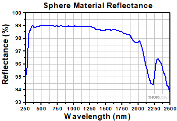
Click to Enlarge
Integrating Sphere Material Reflectance
Insights into Best Lab Practices
Scroll down to read about things to consider when building integrating spheres into setups and analyzing data results.
- Ultraviolet and Blue Fluorescence Emitted by Integrating Spheres
- Sample Substitution Errors
Click here for more insights into lab practices and equipment.
Ultraviolet and Blue Fluorescence Emitted by Integrating Spheres
Click to Enlarge
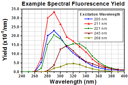
Figure 1: Typical yields at each wavelength are around four orders of magnitude lower than the excitation wavelength. [4]
The spectral fluorescence yield relates the intensity of the fluorescence emitted within the integrating sphere with the intensity of the excitation wavelength. The yield is calculated by dividing the wavelength-dependent, total fluorescence excited over the entire interior surface of the sphere by the intensity of the light excitation.
Data were kindly provided by Dr. Ping-Shine Shaw, Physics Laboratory, National Institute of Standards and Technology, Gaithersburg, MD 20899, USA.
A material of choice for coating the light-diffusing cavities of integrating spheres is polytetrafluoroethylene (PTFE). This material, which is white in appearance, is favored for reasons including its high, flat reflectance over a wide range of wavelengths (see the Specs tab for details) and chemical inertness.
However, it should be noted that integrating spheres coated with both PTFE and barium sulfate, which is an alternative coating with lower reflectance, emit low levels of ultraviolet (UV) and blue fluorescence when irradiated by UV light. [1-3]
Hydrocarbons in the PTFE Fluoresce
It is not the PTFE that fluoresces. The sources of the UV and blue fluorescence are hydrocarbons in the PTFE. Low levels of hydrocarbon impurities are present in the raw coating material, and pollution sources deposit additional hydrocarbon contaminants in the PTFE material of the integrating sphere during its use and
Fluorescence Wavelength Bands and Strength
Researchers at the National Institute of Standards and Technology (NIST) have investigated the fluorescence excited by illuminating PTFE-coated integrating spheres. The total fluorescence output by the integrating sphere was measured with respect to fluorescence wavelength and excitation wavelength. The maximum fluorescence was approximately four orders of magnitude lower than the intensity of the exciting radiation.
The UV and blue fluorescence from PTFE is primarily excited by incident wavelengths in a 200 nm to 300 nm absorption band. The fluorescence is emitted in the 250 nm to 400 nm wavelength range, as shown by Figure 1. These data indicate that increasing the excitation wavelength decreases the fluorescence emitted at lower wavelengths and changes the shape of the fluorescence spectrum.
As the levels of hydrocarbon contaminants in the PFTE increase, fluorescence increases. A related effect is a decrease of the light output by the integrating sphere over the absorption band wavelengths, due to more light from this spectral region being absorbed. [1, 3]
Impact on Applications
The UV and blue fluorescence from the PTFE has negligible effect on many applications, since the intensity of the fluorescence is low and primarily excited by incident wavelengths <300 nm. Applications sensitive to this fluorescence include long-term measurements of UV radiation throughput, UV source calibration, establishing UV reflectance standards, and performing some UV remote sensing tasks. [1]
Minimizing Fluorescence Effects
Minimizing and stabilizing the fluorescence levels requires isolating the integrating sphere from all sources of hydrocarbons, including gasoline- and diesel-burning engine exhaust and organic solvents, such as naphthalene and toluene. It should be noted that, while hydrocarbon contamination can be minimized and reduced, it cannot be eliminated. [1]
Since the history of each integrating sphere's exposure to hydrocarbon contaminants is unique, it is not possible to predict the response of a particular sphere to incident radiation. When an application is negatively impacted by the fluorescence, calibration of the integrating sphere is recommended. A calibration procedure described in [4] requires a light source with a well-known spectrum that extends across the wavelength region of interest, such as a deuterium lamp or synchrotron radiation, a monochromator, a detector, and the integrating sphere.
References
[1] Ping-Shine Shaw, Zhigang Li, Uwe Arp, and Keith R. Lykke, "Ultraviolet characterization of integrating spheres," Appl.Opt. 46, 5119-5128 (2007).
[2] Jan Valenta, "Photoluminescence of the integrating sphere walls, its influence on the absolute quantum yield measurements and correction methods," AIP Advances 8, 102123 (2018).
[3] Robert D. Saunders and William R. Ott, "Spectral irradiance measurements: effect of UV-produced fluorescence in integrating spheres," Appl. Opt. 15, 827-828 (1976).
[4] Ping-Shine Shaw, Uwe Arp, and Keith R. Lykke, "Measurement of the ultraviolet-induced fluorescence yield from integrating spheres," Metrologia 46, S191 - S196 (2009).
Date of Last Edit: Dec. 4, 2019
Sample Substitution Errors
Click to Enlarge
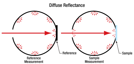
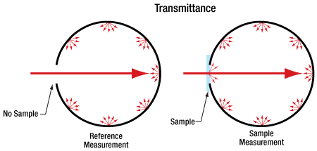
Figure 2: Measuring diffuse sample transmittance and reflectance as shown above can result in a distorted sample spectrum due to sample substitution error. The problem is that the reflectivity over the sample area is different during the reference and sample measurements.
Click to Enlarge
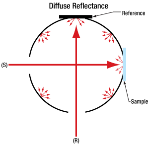
Figure 3: The above configuration is not susceptible to sample substitution error, since the interior of the sphere is the same for reference and sample measurements. During the reference measurement the light travels along (R), and no light is incident along (S). The opposite is true when a sample measurement is made.
Absolute transmittance and absolute diffuse reflectance spectra of optical samples can be found using integrating spheres. These spectra are found by performing spectral measurements of both the sample of interest and a reference.
Measurement of a reference is needed since this provides the spectrum of the illuminating light source. Obtaining the reference scan allows the spectrum of the light source to be subtracted from the sample measurement.
The light source reference measurement is made with no sample in place for transmittance data and with a highly reflective white standard reference sample in place for reflectance measurements.
Sample substitution errors incurred while acquiring the sample and reference measurement sets can negatively effect the accuracy of the corrected sample spectrum, unless the chosen experimental technique is immune to these errors.
Conditions Leading to Sample Substitution Errors
An integrating sphere's optical performance depends on the reflectance at each point on its entire inner surface. Often, a section of the sphere's inner wall is replaced by the sample when its transmittance and diffuse reflectance spectra are measured (Figure 2). However, modifying a section of the inner wall alters the performance of the integrating sphere.
Sample substitution errors are a concern when the measurement procedure involves physically changing one sample installed within the sphere for another. For example, when measuring diffuse reflectance (Figure 2, bottom), a first measurement might be made with the standard reference sample mounted inside the sphere. Next, this sample would be removed and replaced by the sample of interest, and a second measurement would be acquired. Both data sets would then be used to calculate the corrected absolute diffuse reflectance spectrum of the sample.
This procedure would result in a distorted absolute sample spectrum. Since the sample of interest and the standard reference have different absorption and scattering properties, exchanging them alters the reflectivity of the integrating sphere over the samples' surface areas. Due to the average reflectivity of the integrating sphere being different for the two measurements, they are not perfectly compatible.
Solution Option: Install Sample and Reference Together
One experimental technique that avoids sample substitution errors acquires measurement data when both sample and reference are installed inside the integrating sphere at the same time. This approach requires an integrating sphere large enough to accomodate the two, as additional ports.
The light source is located external to the integrating sphere, and measurements of the sample and standard reference are acquired sequentially. The specular reflection from the sample, or the transmitted beam, is often routed out of the sphere, so that only the diffuse light is detected. Since the inner surface of the sphere is identical for both measurements, sample substitution errors are not a concern.
Alternate Solution Option: Make Measurements from Sample and Reference Ports
If it is not possible to install both sample and standard references in the integrating sphere at the same time, it is necessary to exchange the installed sample. If this must be done, sample substitution errors can be removed by following the procedure detailed in [1].
This procedure requires a total of four measurements. When the standard sample is installed, measurements are made from two different ports. One has a field of view that includes the sample and the other does not. The sample of interest is then subsituted in and the measurements are repeated. Performing the calculations described in [1] using these measurements removes the sample substitution errors.
References
[1] Luka Vidovic and Boris Majaron, "Elimination of single-beam substitution error in diffuse reflectance measurements using an integrating sphere," J. Biomed.Opt. 19, 027006 (2014).
Date of Last Edit: Dec. 4, 2019
| Posted Comments: | |
stefano lettieri
(posted 2024-10-24 12:22:05.18) Dear Sirs,
I have few questions about 4P4.
1) My samples are powders, and hence I would very much prefer to place the sample port horizontally, with illumination from the dual port provided from above (i.e. vertically). This shall be possible if the sphere housing can rotate about the horixzontal axis, so that the sample port is placed on the bottom. Is it possible to do so? It seems so looking at the photos but I am not sure. Or the orientation of the housing (and ports) is fixed?
2) The number of available fixed ports is decided once and for all? I mean, the 4P4 configuraiton has two mounted (SM1 threaded) ports for the 5 mm holes, while there is a red cap on the other six. Is is possible to remove the red cap and use other ports/exits by purchasing additional (SM1-thereaded) adapters? If yes, where are they on the cathalog? If not, does it mean that once the numer of the fixed ports is decided it remains the same (and I shall eventually purchase a custom sphere do make use of more exits?)
3) Regarding the fixed ports: is 5 mm the diameter of the hole?
Kind regards. jjadvani
(posted 2024-10-25 10:20:21.0) Dear stefano, thank you for contacting Thorlabs. I will reach out to you directly to discuss your application and possibility for the solution to your requirement. Lili Wang
(posted 2023-07-17 12:26:36.947) I have a question regarding 4P4. Do you have a compatible sample holder for thin film samples for the integrating sphere, like 4P20 for cuvettes? Or are there other ways to hold thin film samples in the sphere? Please contact me with answers since I am interested in this sphere for PLQY measurements on thin films. hchow
(posted 2023-07-18 10:21:25.0) Dear Ms. Wang, thank you for your valuable feedback. At present time, we do not have an alternative product that allows one to hold thin film samples within the cavity of the sphere. Rogie Bernabe
(posted 2023-04-10 14:35:24.1) Good day,
I'm Rogie Bernabe, aspiring optomechanical engineer and currently proposing a optics equipment for our upcoming imaging test for University applications. May I ask for consultation with regards to integrating sphere? I would like to ask for assistance for the complete BOM set-up for the integrating sphere (4P3) so we could properly budget the system. The minimum test that we are proposing are: Spatial Resolution Test, Spectral Calibration Test, & Radiometric Calibration Test. Please advise for the complete package or set. I've initially started to ask for official quote with Quotation: TQ0484379. Do note, I've also designing a 3 in 1 set-up, so the proposed Quotation: TQ0484379 is on-going.
Thank you very much,
Rogie Bernabe hchow
(posted 2023-04-12 11:08:54.0) Dear Mr. Bernabe,
thank you for your feedback. As what you are proposing is too complex to discuss here, I shall personally reach out to you to discuss various customisation options with our 4P3 integrating sphere. Thank you. Kevin Stevens
(posted 2023-02-15 10:23:54.94) Hello,
Is there a possibility to have a custom coating for the integration sphere?
We are looking for a practical solution to get ~98% reflectance in the 240-350nm region.
Kind Regards, hchow
(posted 2023-02-16 08:47:55.0) Dear Mr. Stevens, thank you for your feedback. Unfortunately at this time, we are unable to do custom reflective coatings in the cavity of the sphere. Thank you. Heiko Linnenbank
(posted 2022-03-04 07:08:27.08) I am interested in the 4P4 in order to setup a custom R/T measurement system. I was wondering if blank insets for the 5 mm ports and for the 14mm ports are available. I am looking for something like the 2P10 for the samller sphere in order to block the 5 mm and 14 mm parts. soswald
(posted 2022-03-09 02:10:11.0) Dear Heiko,
thank you for your feedback. I have reached out to you directly to discuss your application and the required configuration of the 4P4 in more detail. Alessandro Ruggeri
(posted 2021-12-20 09:01:39.633) Hello,
I was wondering if this integrating sphere has some baffles in the internal surface, to avoid direct path beams, even if it is not clearly stated in the page. In case, it is possible to indicate their position? Thank you and best regards! dpossin
(posted 2021-12-28 05:09:30.0) Dear Alessandro,
Thank you for your feedback. We do not use baffling in our integrating spheres. We limit the angle of incidence to +/- 20° instead. I am reaching out to you to clarify open questions you may have. MIKEL EZQUER
(posted 2021-02-04 10:39:43.553) Dear Sir/Madam,
I write you from CENER (Spain) because we are thinking about purchasing a 4P4 integrating sphere to be used to measure the spectral reflectance of photovoltaic samples.
The wavelength range we need goes from 350nm to 1200nm.
We are going to use 2 spectrorradiometers for other supplier (CAS-140 CT of Instrument systems)
We are planning to use your OSL2 halogen lamp as a light soruce to be used in the measurement. Do you think the temporal stability of this lamp is good enough for this kind of application?
In order to connect the lamp to the 4P13 port of the sphere we would use the standard fiber bundle, but we do not know if we need some kind of adapter to connect the bundle to the 4P13(SM1) port, or some collimator piece in order to focuse the light into the 4P11 port with the sample to be measured.
Finally, as we have 2 different spectrorradiometers, we would need a bifurcated fiber bundle to carry the reflected light from the sphere to the spectrorradiometers. Which would be your recommendation for this concrete application?
If you have any additional suggestion o recommendation about the best combination of equipment to carry out this reflectance measurements, we would be very pleased.
Than you very much in advance!
Best regards! MKiess
(posted 2021-02-05 08:57:58.0) Dear Mikel, thank you very much for your inquiry. I have contacted you directly to discuss your application in detail and thus assemble the most suitable products for your purpose. |

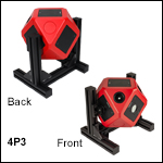
- 4P3: Pre-Configured for Light Measurement
- 4P4: Pre-Configured for Reflection Measurement
- XE25 Rail System Stand Included
The 4P3 sphere is pre-configured for light measurement, designed so that the sphere is continuous opposite the Ø1" port that would be used for a light source. This reduces the probability of primary reflections occurring on a seam around a port plug.
The 4P4 sphere is pre-configured for reflection measurements, as shown in the middle diagram above. An SM1-threaded, Ø1" port insert allows samples in SM1-threaded mounts (for example, an SM1L05 lens tube) to be positioned opposite a light source. Two Ø14 mm ports on the opposing face are designed with an 8° geometry so that light input to one Ø14 mm port will reflect off the sample in the Ø1" port, allowing the direct reflection to be detected from the second Ø14 mm port. Indirect reflectance can be detected using one of the two fixed Ø5 mm ports.
These spheres are shipped pre-mounted to the included rail system stand with M4 cap screws. To unmount the sphere, the screws can be removed using a 3 mm hex key or balldriver. The interchangeable port inserts are each fastened by two M3 x 0.5 screws; to exchange the default inserts with other inserts, loosen the screws using a 2 mm (5/64") hex key or balldriver.

Click to Enlarge
Interior Side of 4P13 Insert
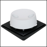
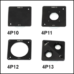
These easily interchangeable port inserts are designed for use with Thorlabs Ø100 mm Modular Integrating Spheres. Two included M3 x 0.5 screws secure each insert to the sphere, allowing the insert of any modular face to be swapped out using a 2 mm (5/64") hex ball driver. The sphere-facing sides of the 4P10, 4P11, and 4P13 inserts have the same radius of curvature and are made of the same highly reflective bulk material as the rest of the sphere, minimizing losses from changes in geometry. The 4P12 insert does not have any bulk material in its design as the aperture is closely matched with the hole in the integrating sphere for the modular face.
Dust caps are included with the 4P11 and 4P13 inserts to protect the sphere from dust and debris when not in use, while the 4P12 insert should be exchanged with a 4P10 port plug insert for the same purpose. However, ports closed with caps or left open will disrupt the uniform reflectance properties of the sphere. Prior to operation of the sphere, any unused, open port insert should be exchanged for a 4P10 insert for optimal performance.
If the inserts available from stock are not suitable for your application, please contact Tech Support to inquire about custom inserts.
| Item # | Port Size | Threading | Cage System Compatibility | Dust Cap(s) |
|---|---|---|---|---|
| 4P10 | N/A | N/A | N/A | N/A |
| 4P11 | Ø1" | SM1 | Four 4-40 Taps for 30 mm Cage | Included |
| 4P12 | Ø2" | SM2 | Four 4-40 Taps for 60 mm Cage | None |
| 4P13 | Two Ø14 mm, 8° Geometrya | SM1 | None | Included |


Click to Enlarge
Integrating Sphere Shown with 4P20 Insert and Cuvette Installed
Click to Enlarge
Assembled 4P20 Cuvette Holder
Port Insert (Cuvette Sold Separately)
Click to Enlarge
Cuvette Holder Separated from Insert Base
- Mount 12.5 mm x 12.5 mm Cuvettes Inside Ø100 mm Integrating Spheres
- Quick-Release Cuvette Retention Mechanism
- Adjustable Cuvette Orientation and Depth
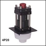
The 4P20 Cuvette Holder Port Insert holds cuvettes inside our Ø100 mm Modular Integrating Spheres. The insert is compatible with our 12.5 mm x 12.5 mm cuvettes with 10 mm path lengths (sold separately). Cuvettes with or without caps can be used to analyze liquid samples with the cuvette in an upright position. If a cap is to be used, we recommend using a cuvette with an airtight stopper rather than a top cap, as the latter tends to get stuck in the insert's cuvette retention mechanism. Cuvettes from 11.8 mm square to 12.8 mm square are supported, and the bottom of a 45 mm long cuvette with a 3 mm tall cap sits approximately at the center of the Ø100 mm integrating sphere when the holder is fully retracted.
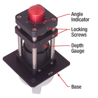
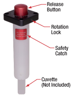
The 4P20 insert is comprised of the base and cuvette holder, which can be separated for cuvette replacement while the base remains attached to the integrating sphere. The holder can be rotated 360°, and its insertion depth into the sphere can be adjusted up to 24 mm to alter the position of the cuvette. An angle indicator and depth gauge are engraved on the insert as shown in the second photo above. The angle indicator is engraved every 5° between ±45° and then at 90°, 180°, and 270°. The depth gauge is engraved with marks spaced 1 mm apart. Setscrews with 2.0 mm (5/64") hexes are present on the holder and base cage plates to lock the rotation and depth. The holder also has a release button and safety catch for secure retention and rapid removal of the cuvette. For more details, please refer to the user guide.
Two included M3 x 0.5 screws [2.0 mm (5/64") hex] are used to secure the insert to the integrating sphere in place of its modular top face. The sphere-facing side of the insert surrounding the cuvette retention mechanism has the same radius of curvature and is made of the same highly reflective bulk material as the rest of the sphere, minimizing losses from changes in geometry.
If the inserts available from stock are not suitable for your application, please contact Tech Support to inquire about custom inserts.
 Products Home


 Zoom
Zoom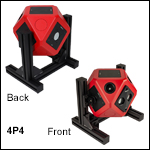
 Modular Ø100 mm Integrating Spheres