Round Wedge Prisms

- Used Primarily in Laser Beam Steering Applications
- Available with Three Broadband AR Coatings
- Material: N-BK7, Grade A
- Surface Flatness: λ/10
PS814
PS810
PS812
Application Idea
PS814 Prism Mounted in a PRM1 Rotation Mount Using an SM1W189 Shim and SM1RR Retaining Ring
SM1W189
Mounting Shim for PS814

Please Wait
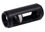
Click to Enlarge SM1W1122 Mounting Shim Being Used with an SM1RR Retaining Ring to Mount a PS812 Prism in an SM1 Lens Tube
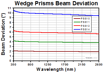
Thorlabs' Wedge Prisms are ideal for laser beam steering applications. Also known as Risley prisms, these optics deflect a beam normal to the prism's perpendicular surface through an angular deviation ranging from 2° to 10°. Please refer to the Wedged Prism Specs tab for the angular deviation of each wedge prism. Thorlabs' wedge prisms can be purchased uncoated or coated with one of three standard broadband AR coatings on both the flat and angled surfaces.
Wedge prisms can be used individually or in combination with another wedge prism for beam steering. For more details and to see a sample application, click on the Application Idea tab above.
Mounting
Mounting Shims are offered below to provide a flat, uninterrupted mounting surface between a wedge prism and one of our retaining rings. These shims have a wedge on one side to ensure that the optic is properly mounted within an SM1 lens tube or rotation mount when secured with a retaining ring.
| Click on the red Document icon next to the item numbers below to access the Zemax file download. Our entire Zemax Catalog is also available. |
| General Specifications | |||
|---|---|---|---|
| Material | N-BK7a | ||
| Dimensional Tolerance | ±0.15 mm | ||
| Diameter | 25.4 mm +0.0/-0.3 mm | ||
| Clear Aperture | >80% of Diameter | ||
| Angular Tolerance | ±30 arcsec | ||
| Surface Quality of Polished Surfaces | 40-20 Scratch-Dig | ||
| Surface Flatness | λ/10 at 633 nm | ||
| Design Wavelength | 633 nm | ||
| Thin Edge of Wedge | 3.00 mm | ||
| AR Coatingb | -A | 350 - 700 nm | |
| -B | 650 - 1050 nm | ||
| -C | 1050 - 1700 nm | ||
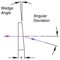
| Item # | Angular Deviation |
Thickness (T) (mm) | Wedge Angle | Powera (Diopter) | Compatible Mounting Shim |
|---|---|---|---|---|---|
| PS810 | 2° | 4.72 | 3° 53' | 3.5 | SM1W353 |
| PS811 | 4° | 6.43 | 7° 41' | 7.0 | SM1W741 |
| PS812 | 6° | 8.11 | 11° 22' | 10.5 | SM1W1122 |
| PS814 | 10° | 11.33 | 18° 9' | 17.4 | SM1W189 |
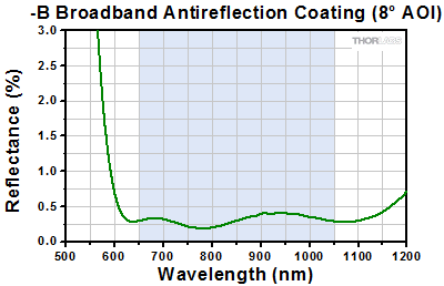
Click to Enlarge
Click Here for Raw Data
The blue shaded region indicates the specified 650 - 1050 nm wavelength range for optimum performance.
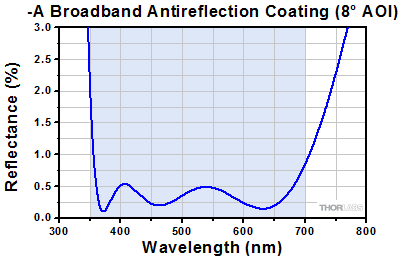
Click to Enlarge
Click Here for Raw Data
The blue shaded region indicates the specified 350 - 700 nm wavelength range for optimum performance.
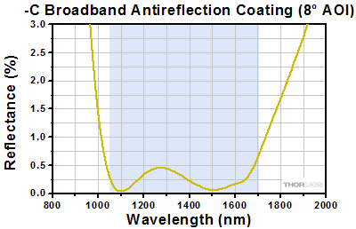
Click to Enlarge
Click Here for Raw Data
The blue shaded region indicates the specified 1050 - 1700 nm wavelength range for optimum performance.
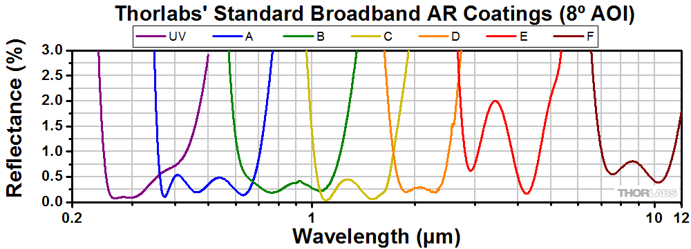
Application Ideas
- Introduction and Setup
- Tracing a Circle with One Prism
- Tracing a Circle with Two Prisms
- Tracing a Spiral with Two Prisms
Introduction and Setup
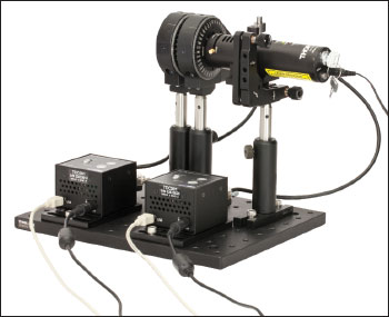
Wedge prisms are designed to be used, either individually or in a pair, for beam steering applications. This is done by individually controlling the rotation of each prism using our PRM1Z8 motorized rotation stages. The tables below correspond to either the imperial or metric product list for the configuration pictured to the right. Clicking on the item number will bring up a pop-up window with more information about that component.
An Application Note was prepared to describe this process in further detail, and will be referenced periodically here. For a full download of the Application Note, click the button at the upper right of this tab. To the upper right is also a download for an Excel spreadsheet which can be used to model a Risley Prism Scanner.
Note: The photo to the right shows a previous generation TDC001 T-Cube and previous-generation KPS101 Power Supplies.
Tracing a Circle with One Prism
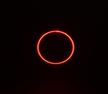
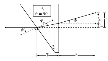
For this application, only one prism was mounted in a rotation mount. The incoming beam was deviated off axis by the wedge prism. Once the rotation mount was activated, the wedge prism was spun about the optical axis, which caused the deviated beam to trace out a small circle, as shown in the long-exposure photograph to the right. The radius of this circle can be calculated as:

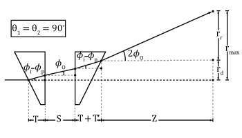
This is equation 9 in the Application Note linked above. In this equation r' is this circle's radius, S is the distance from the last surface of the prism to the scanning surface, T is the center thickness of the prism, Φo is the beam angle relative to the original optical axis after exiting the second surface of the prism, Φi is the angle created from the beam's incidence on the first surface of the prism according to Snell's Law, and Φp is the resulting angle the beam takes inside the prism relative to the first surface's normal according to Snell's Law.
Tracing a Circle with Two Prisms
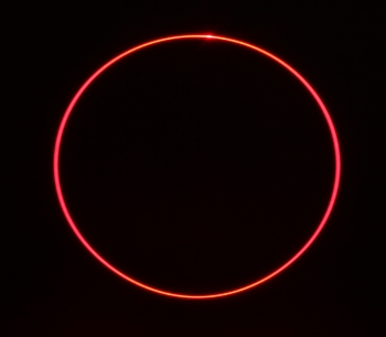
For this application, the rotation mounts are set so that the wedges of both prisms are aligned to the home position, where both prisms' thickest sections are vertical. Since each prism will deviate the beam by the deviation angle, the total beam deviation for two prisms with the wedges aligned will be approximately twice the size. If both prisms are rotated at the same rate and in the same direction, the beam will trace out a circle which is approximately twice the size of the circle traced out by a single prism. The long-exposure photograph to the right was taken with the prism assembly at the same distance from the screen as the one-prism circle above. Notice that the circle in the two-prism case is about twice the diameter of the one formed with one prism. The radius of this circle can be calculated as:

This is equation 18 in the Application Note linked above. In this parametric equation, rmax is the radius of this circle (any subsequent shape created by this setup is enclosed by this radius), T is the middle thickness of the fist prism, T' is the effective thickness of prism 2 after the deviated beam travels through it, Φi is the angle created from the beam's incidence on the first surface of the fist prism according to Snell's Law, Φp is the resulting angle the beam takes inside the prism relative to the first surface's normal according to Snell's Law, z is the distance from the second surface of the second prism to the scanning surface, S is the distance between the prisms, and Φo is the beam angle relative to the original optical axis after exiting the second surface of the first prism.
Tracing a Spiral with Two Prisms
It can be shown that a large variety of shapes can be traced while rotating the two prisms at constant speeds. These shapes are dictated by the equation:

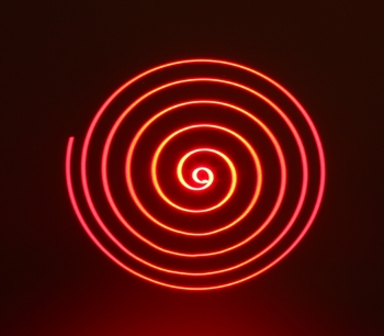
This is equation 21 in the Application Note linked above; please reference that Application Note or the accompanying spreadsheet for the definitions of these variables. As an example, the long-exposure photograph to the right shows two wedge prisms being used to trace out a spiral. This was realized by first setting the beam to be undeviated, and then having the prisms rotate in the same direction, with one prism set to rotate 0.5 deg/s faster than the other. This, and many other shapes, can be created on the "Third Approx." sheet of the downloadable Excel sheet above. To create this spiral, try inputting 25 deg/s to ω1 (rotation speed of prism 1), 24.5 deg/s to ω2 (rotation speed of prism 2), and 80 seconds to t (run time), with a Δθ (home position offest) of 180 degrees.
| Posted Comments: | |
Ha CK
(posted 2023-07-13 11:36:52.753) Is there any information about polarization dependence of prism wedge products? cdolbashian
(posted 2023-07-21 11:45:35.0) Thank you for reaching out to us with this inquiry. The material is just a cut N-BK7 substrate and the performance will have little dependence on the incoming polarization. On the other hand, the transmission amplitudes of orthogonal polarization states will vary according to the Fresnel coefficient calculations. I have contacted you directly to discuss this further. Bruce Wei
(posted 2023-06-08 10:14:32.89) We used it under the this Laser source ( 355 nm 10 ps 35 W, beam diameter : 2 mm ) and found it damaged. Is the power higher than the LIDT of the optics? cdolbashian
(posted 2023-06-12 01:52:42.0) Thank you for reaching out to us with this inquiry! These components are N-BK7 glass with or without a coating. Presuming that you damaged the -A coated prism, this is not surprising as those laser parameters yield a high peak power and energy density. It seems your email was undeliverable, so if you want to share more about your application/implementation of this component, please contact techsupport@thorlabs.com. Amir Hen
(posted 2023-05-23 12:01:55.94) Please indicate on which side of the prism is the AR coating. cdolbashian
(posted 2023-05-24 08:35:19.0) Thank you for reaching out to us! These prisms are coated on both planar faces. Abdel-Farid Mamadou Idrissou
(posted 2022-05-24 21:25:16.047) Hi there,
I am e researcher in a technology entreprise.
I would like to make a linear movement with two prisms at a frequency of around 1300, is there a set-up already ready? jdelia
(posted 2022-06-01 03:48:05.0) Thank you for contacting Thorlabs. I have reached out to you directly to discuss your application. Sebastian Gründel
(posted 2020-04-16 02:25:57.783) Is it also an possible option to get just one side coated? YLohia
(posted 2020-04-16 09:25:47.0) Hello, thank you for contacting Thorlabs. Custom items can be requested by emailing us at techsupport@thorlabs.com. I have reached out to you directly to discuss the possibility of offering this. PoYen Lin
(posted 2019-08-28 06:28:51.177) Dear Sirs,
I am interested in the application of wdege prism (PS814-B). In its application note, I read the max. rotation velocity of the motor rotation mount (PRM1/MZ8) is 25 degree/sec.
Does it mean that if I want to use this motorized mount to generate a laser ring , it will take around 14.4 sec? (360/25 =14.4)
Thank you.
PoYen nbayconich
(posted 2019-08-28 10:54:39.0) Thank you for contacting Thorlabs. Yes to trace a circular beam path using the PS814-B and the PRM1-Z8 rotational mount it would take about 14.4 seconds to complete a full revolution. If you are looking for a faster stage option we also have the DDR25 rotational mount which can move at 5Hz or 5 revolutions/second. We also have galvo systems for faster beam steering applications. nick.walkden
(posted 2018-07-17 14:55:31.533) Hi,
Do you make a 52mm/2inch diameter version of the wedge prism to fit your 52mm optical tube?
Thanks
Nick YLohia
(posted 2018-07-19 09:48:58.0) Hi Nick, I will reach out to you directly regarding the possibility of offering 2" diameter versions of our wedge prisms. user
(posted 2017-11-02 15:47:22.733) It would be very helpful with orientation if the thinnest part of prism was marked on the edge of the optic. nbayconich
(posted 2017-11-15 04:34:57.0) Thank you for contacting Thorlabs. We can provide these prisms with markings upon request. For more information about quoting customized optics please provide us your e-mail address or contact us at techsupport@thorlabs.com a.kuhn
(posted 2017-07-03 10:50:56.3) Hello,
can you supply the wedge prism in fused silica rather than BK7?
Regards
Andreas nbayconich
(posted 2017-07-27 08:17:48.0) Thank you for contacting Thorlabs. I will reach out to you directly about our custom capabilities. sergepl
(posted 2016-09-06 02:02:11.15) In PS810 PDF drawing specified wrong thickness 4.2mm instead of 4.72mm. tfrisch
(posted 2016-09-08 08:49:37.0) Hello, thank you for pointing out the inconsistency between our drawing and spec. We are working on updating to the correct information in all sources. Avenellj
(posted 2015-12-16 12:27:21.757) Can I get a prism wedge in 0.54 degrees besembeson
(posted 2015-12-16 03:49:41.0) Response from Bweh at Thorlabs USA: Thanks for contacting Thorlabs. I will follow-up regarding quoting this special for you. cesar.eduardo.garza.lozano
(posted 2014-05-19 15:20:55.5) PS810 product do not show any information about the refractive index acordnig to wavelenght. what isthe refractive index of PS810 if i would use a 808nm laser?
thanks in advance
Cesar Garza myanakas
(posted 2014-05-19 12:47:50.0) Response from Mike at Thorlabs: Thank you for your feedback. We are currently working to have this information available on our wedge prism page. The index of refraction of N-BK7, which is the glass used for our wedge prisms, at 808 nm is about 1.51. If you need more information, a full presentation of all of our optical substrates, including N-BK7, can be found here: http://www.thorlabs.com/newgrouppage9.cfm?objectgroup_id=6973. I have also contacted you directly. strangek
(posted 2013-07-23 16:17:39.213) What is the transmitted wavefront distortion of these prisms? Thanks cdaly
(posted 2013-07-24 16:34:00.0) Response from Chris at Thorlabs: Thank you for your feedback. We do not have a tested value for the transmitted wave front error, but with a surface flatness value of lamda/10. The worst case should not be any higher than lamda/5, not accounting for tilt due to the wedge. bdada
(posted 2011-11-04 11:04:00.0) Response from Buki at Thorlabs:
Thank you for participating in our Feedback Forum. You can fill the area of the circle by rotating the 2 prisms. One prism gives you the ability to rotate and generate a hollow cone angle, while two prims will double your angular deviation and allow you to hit any point within that solid cone angle. In this case, the proper rotation of the 2 prisms would allow you to trace the path of an archimedes' spiral.
We will update the image on our website to make this clearer. yannick.sudrie
(posted 2011-11-02 00:19:13.0) Dear sir,
there is something i do not understand about your Wedge Prism overwiew. I can read :"As both Wedges are rotated, the area of a circle is filled."
I am trying to find a way to plot an archimedes' spiral with a laser and i am not sure i am be able to do this with your two wedges prism; would you clarifi this point please does it mean :
- it's possible to plot a spot every where inside the area of a circle on the cone base ? ex : if 4xtheta = circle diameter = 1 and i wana plot a spot at coordinated (0;0) the center or (0;0.5)on the edge ... i will be able to put the plot where i want inside the circle area build by the cone if i am 'playing' with two prisms' angles from 0 to 2pi.
OR
- I can only put a plot on 4xtheta = circle diameter = 1 on the circle edge line only ?
thanks for your help.
sudrie Thorlabs
(posted 2010-11-05 22:27:09.0) Response from Javier at Thorlabs to eee: Thank you very much for your feedback. We currently do not offer mounting rings specifically designed for the wedge prisms. However, in order to mount one of these prisms onto the PRM1, you can use (4) ER cage rods and the ARV1 cage clamp. Links below:
http://www.thorlabs.com/NewGroupPage9.cfm?ObjectGroup_ID=180
http://www.thorlabs.com/NewGroupPage9.cfm?ObjectGroup_ID=1330&pn=ARV1 eee
(posted 2010-11-05 09:08:00.0) What about mounting ? It would be nice if each of these wedged prisms would have a complementary wedged metallic ring included, e.g. for mounting in PRM1. |
Selection Guide for Prisms
Thorlabs offers a wide variety of prisms, which can be used to reflect, invert, rotate, disperse, steer, and collimate light. For prisms and substrates not listed below, please contact Tech Support.
Beam Steering Prisms
| Prism | Material | Deviation | Invert | Reverse or Rotate | Illustration | Applications |
|---|---|---|---|---|---|---|
| Right Angle Prisms | N-BK7, UV Fused Silica, Calcium Fluoride, or Zinc Selenide | 90° | 90° | No | 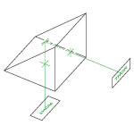 |
90° reflector used in optical systems such as telescopes and periscopes. |
| 180° | 180° | No | 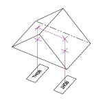 |
180° reflector, independent of entrance beam angle. Acts as a non-reversing mirror and can be used in binocular configurations. |
||
| TIR Retroreflectors (Unmounted and Mounted) and Specular Retroreflectors (Unmounted and Mounted) |
N-BK7 | 180° | 180° | No | 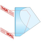 |
180° reflector, independent of entrance beam angle. Beam alignment and beam delivery. Substitute for mirror in applications where orientation is difficult to control. |
| Unmounted Penta Prisms and Mounted Penta Prisms |
N-BK7 | 90° | No | No | 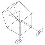 |
90° reflector, without inversion or reversal of the beam profile. Can be used for alignment and optical tooling. |
| Roof Prisms | N-BK7 | 90° | 90° | 180o Rotation | 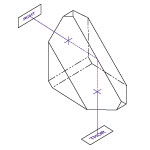 |
90° reflector, inverted and rotated (deflected left to right and top to bottom). Can be used for alignment and optical tooling. |
| Unmounted Dove Prisms and Mounted Dove Prisms |
N-BK7 | No | 180° | 2x Prism Rotation | 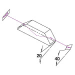 |
Dove prisms may invert, reverse, or rotate an image based on which face the light is incident on. Prism in a beam rotator orientation. |
| 180° | 180° | No | 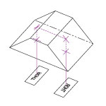 |
Prism acts as a non-reversing mirror. Same properties as a retroreflector or right angle (180° orientation) prism in an optical setup. |
||
| Wedge Prisms | N-BK7 | Models Available from 2° to 10° | No | No |  |
Beam steering applications. By rotating one wedged prism, light can be steered to trace the circle defined by 2 times the specified deviation angle. |
| No | No |  |
Variable beam steering applications. When both wedges are rotated, the beam can be moved anywhere within the circle defined by 4 times the specified deviation angle. |
|||
| Coupling Prisms | Rutile (TiO2) or GGG | Variablea | No | No | 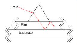 |
High index of refraction substrate used to couple light into films. Rutile used for nfilm > 1.8 GGG used for nfilm < 1.8 |
Dispersive Prisms
| Prism | Material | Deviation | Invert | Reverse or Rotate | Illustration | Applications |
|---|---|---|---|---|---|---|
| Equilateral Prisms | F2, N-F2, N-SF11, Calcium Fluoride, or Zinc Selenide |
Variablea | No | No | 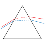 |
Dispersion prisms are a substitute for diffraction gratings. Use to separate white light into visible spectrum. |
| Dispersion Compensating Prism Pairs | Fused Silica, Calcium Fluoride, SF10, or N-SF14 | Variable Vertical Offset | No | No |  |
Compensate for pulse broadening effects in ultrafast laser systems. Can be used as an optical filter, for wavelength tuning, or dispersion compensation.
|
| Pellin Broca Prisms | N-BK7, UV Fused Silica, or Calcium Fluoride |
90° | 90° | No |  |
Ideal for wavelength separation of a beam of light, output at 90°. Used to separate harmonics of a laser or compensate for group velocity dispersion. |
Beam Manipulating Prisms
| Prism | Material | Deviation | Invert | Reverse or Rotate | Illustration | Applications |
|---|---|---|---|---|---|---|
| Anamorphic Prism Pairs | N-KZFS8 or N-SF11 |
Variable Vertical Offset | No | No | 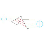 |
Variable magnification along one axis. Collimating elliptical beams (e.g., laser diodes) Converts an elliptical beam into a circular beam by magnifying or contracting the input beam in one axis. |
| Axicons (UVFS, ZnSe) | UV Fused Silica or Zinc Selenide |
Variablea | No | No |
Creates a conical, non-diverging beam with a Bessel intensity profile from a collimated source. |
Polarization Altering Prisms
| Prism | Material | Deviation | Invert | Reverse or Rotate | Illustration | Applications |
|---|---|---|---|---|---|---|
| Glan-Taylor, Glan-Laser, and α-BBO Glan-Laser Polarizers | Glan-Taylor: Calcite Glan-Laser: α-BBO or Calcite |
p-pol. - 0° s-pol. - 112°a |
No | No | 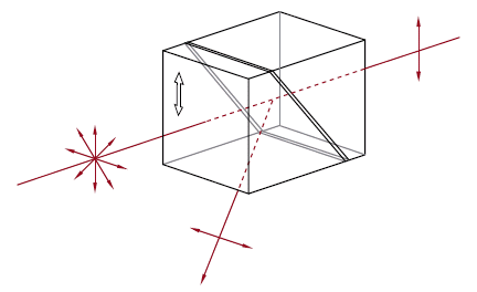 |
Double prism configuration and birefringent calcite produce extremely pure linearly polarized light. Total Internal Reflection of s-pol. at the gap between the prism while p-pol. is transmitted. |
| Rutile Polarizers | Rutile (TiO2) | s-pol. - 0° p-pol. absorbed by housing |
No | No | 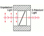 |
Double prism configuration and birefringent rutile (TiO2) produce extremely pure linearly polarized light. Total Internal Reflection of p-pol. at the gap between the prisms while s-pol. is transmitted.
|
| Double Glan-Taylor Polarizers | Calcite | p-pol. - 0° s-pol. absorbed by housing |
No | No | 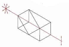 |
Triple prism configuration and birefringent calcite produce maximum polarized field over a large half angle. Total Internal Reflection of s-pol. at the gap between the prism while p-pol. is transmitted. |
| Glan Thompson Polarizers | Calcite | p-pol. - 0° s-pol. absorbed by housing |
No | No | 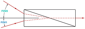 |
Double prism configuration and birefringent calcite produce a polarizer with the widest field of view while maintaining a high extinction ratio. Total Internal Reflection of s-pol. at the gap between the prism while p-pol. is transmitted. |
| Wollaston Prisms and Wollaston Polarizers |
Quartz, Magnesium Fluoride, α-BBO, Calcite, Yttrium Orthovanadate | Symmetric p-pol. and s-pol. deviation angle |
No | No | 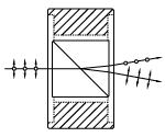 |
Double prism configuration and birefringent calcite produce the widest deviation angle of beam displacing polarizers. s-pol. and p-pol. deviate symmetrically from the prism. Wollaston prisms are used in spectrometers and polarization analyzers. |
| Rochon Prisms | Magnesium Fluoride or Yttrium Orthovanadate |
Ordinary Ray: 0° Extraordinary Ray: deviation angle |
No | No | 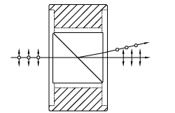 |
Double prism configuration and birefringent MgF2 or YVO4 produce a small deviation angle with a high extinction ratio. Extraordinary ray deviates from the input beam's optical axis, while ordinary ray does not deviate. |
| Beam Displacing Prisms | Calcite | 2.7 or 4.0 mm Beam Displacement | No | No | 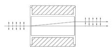 |
Single prism configuration and birefringent calcite separate an input beam into two orthogonally polarized output beams. s-pol. and p-pol. are displaced by 2.7 or 4.0 mm. Beam displacing prisms can be used as polarizing beamsplitters where 90o separation is not possible. |
| Fresnel Rhomb Retarders | N-BK7 | Linear to circular polarization Vertical Offset |
No | No | 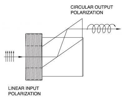 |
λ/4 Fresnel Rhomb Retarder turns a linear input into circularly polarized output. Uniform λ/4 retardance over a wider wavelength range compared to birefringent wave plates. |
| Rotates linearly polarized light 90° | No | No | 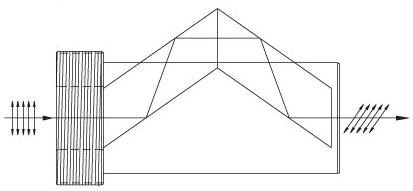 |
λ/2 Fresnel Rhomb Retarder rotates linearly polarized light 90°. Uniform λ/2 retardance over a wider wavelength range compared to birefringent wave plates. |
Beamsplitter Prisms
| Prism | Material | Deviation | Invert | Reverse or Rotate | Illustration | Applications |
|---|---|---|---|---|---|---|
| Beamsplitter Cubes | N-BK7 | 50:50 splitting ratio, 0° and 90° s- and p- pol. within 10% of each other |
No | No | 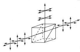 |
Double prism configuration and dielectric coating provide 50:50 beamsplitting nearly independent of polarization. Non-polarizing beamsplitter over the specified wavelength range. |
| Polarizing Beamsplitter Cubes | N-BK7, UV Fused Silica, or N-SF1 | p-pol. - 0° s-pol. - 90° |
No | No | 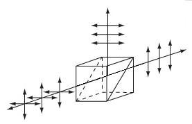 |
Double prism configuration and dielectric coating transmit p-pol. light and reflect s-pol. light. For highest polarization use the transmitted beam. |

Click for Details
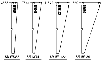
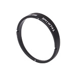
Four Wedge Angles are Available that Match our Wedged Prisms
Click to Enlarge
Each Shim Includes Engraved Witness Lines and Spanner Wrench Slots
- Mount Ø1" Wedge Prisms in SM1-Threaded Lens Tubes or Rotation Mounts
- Four Wedge Angles Available to Match Our Wedge Prisms:
- 3° 53' for PS810 Wedge Prisms
- 7° 41' for PS811 Wedge Prisms
- 11° 22' for PS812 Wedge Prisms
- 18° 9' for PS814 Wedge Prisms
- Mount Planar Optics at an Angle Within an SM1 Lens Tube
- Spanner Wrench Slots for Easy Positioning
Click to Enlarge
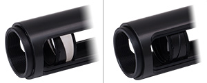
The left image shows one shim being used to mount a wedge prism, while the right image shows two shims being used to mount a filter at an angle to reduce back reflections. An SM1L30C slotted lens tube is used to help confirm the proper fit.
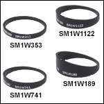
Thorlabs' Wedge Prism Mounting Shims are designed to provide a flat, uninterrupted mounting surface between a Ø1" wedge prism and one of our retaining rings. Normally a retaining ring will only contact a small portion of the wedged optic, potentially causing incorrect seating or unexpected shifts. These shims have a wedge on one side to ensure that the wedged optic is properly mounted within an SM1 lens tube or rotation mount when secured with a retaining ring. The shim does not impinge upon the clear aperture of our wedge prisms, as shown in the drawings to the right. Four shims are available, each with a wedge angle that matches one of our wedge prisms: 3° 53', 7° 41', 11° 22', or 18° 9'.
Each mounting shim has two slots for compatibility with our SPW602 and SPW606 Spanner Wrenches. When aligning these rings within an SM1 lens tube or mount, we recommend holding the mount or lens tube vertically while using a spanner wrench to roughly align the shim's wedge against the optic. When roughly aligned, tighten the retaining ring down until it binds and then slightly loosen it. Alternate between tightening and loosening the retaining ring until the shim and optic are well aligned with one another. Then secure the optic and shim with the retaining ring.
In addition, these shims can be used in pairs to mount Ø1" planar optics, such as filters or windows, at a predefined angle within an SM1 lens tube to reduce back reflections. Simply place the filter between two shims with the same wedge angle and follow the mounting instructions recommended above. When mounting planar optics with this method the optic thickness is critical. The maximum optic thickness is 6 mm when using two SM1W353 mounting shims, or 1 mm when using two SM1W741 or SM1W1122 mounting shims. Due to its large wedge angle, we do not recommend mounting planar filters with the SM1W189. Regardless of the optic thickness, the optic diameter is not large enough, which creates a gap that can allow unfiltered light through.
 Products Home




 Zoom
Zoom Wedge Prisms