Laser Diode Bias-T PCB

- Superimpose an RF Modulation Input onto
a Laser Diode Drive DC Current - Modulation Frequencies from 10 kHz - 1 GHz
T1G
Shown with
Included OSMT
Coaxial Cable
Application Idea
LD1100 Laser
Diode Driver
T1G Bias-T
Laser Diode
Terminals
To Function
Generator
Laser Diode
DC Current
RF Modulation Input
Modulated
Laser Diode
Output

Please Wait
| Specifications | |
|---|---|
| Frequency Range | 10 kHz to 1 GHz |
| Input Impedance | 50 Ω |
| Max DC Current | 110 mA |
| Max RF Current (RMS) | 50 mA |
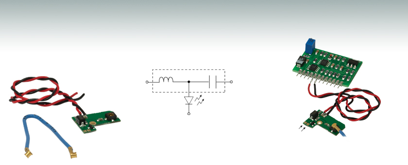
The T1G laser diode bias tee is designed to superimpose a modulation current onto the laser diode DC-supply current, thereby modulating the output power of the laser. This is useful in applications where information is being transmitted over a fiber.
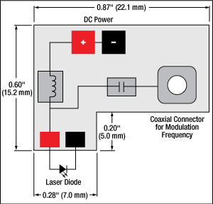
A laser diode driver sets the DC current, and then an alternating voltage is applied to the RF input, which produces a modulated current, allowing the user to achieve the desired modulation amplitude. This bias-T is capable of providing modulation frequencies in the range of 10 kHz to 1 GHz, although the actual frequency range is limited by the impedance network surrounding the laser diode. Using the provided OSMT wire, a function generator can be connected to the OSMT coaxial connector, which has a characteristic impedance of 50 Ω. A DC blocking capacitor and a reverse bias protection diode are included to protect the laser diode.
In addition to the T1G bias tee, Thorlabs manufactures a range of products well suited for building laser controllers, including laser diode drivers, temperature controllers, and evaluation kits. Thorlabs also offers packaged controllers that are ready for integration into rack-mounted systems without additional modification.
| Posted Comments: | |
Hyun-Woo Song
(posted 2024-09-24 14:42:33.44) To whom it may concern,
May I ask if you have a connector (or cable) of OSMT (T1G) for connecting (to BNC) a function generator.
Sincerely,
Hyun-Woo jpolaris
(posted 2024-10-02 05:54:50.0) Thank you for contacting Thorlabs. Unfortunately, we do not have any cables or adapters for OSMT at this time. We have reached out to you directly with some recommendations for 3rd party solutions. Our current collection of premium cables and adapters can be found at the following link: https://www.thorlabs.com/newgrouppage9.cfm?objectgroup_id=9827 Joice Mathew
(posted 2020-03-10 00:23:38.89) Hi,
We have bought T1G board recently from you. how can I actually connect the OSMT connector to a standard function generator coaxial output? I am having a hard time finding an adapter to the OSMT connector. Can you source an OSMT-BNC/OSMT-SMA (or anything else) adapter or help me to find one, please?
Thanks,
Joice. YLohia
(posted 2020-03-10 03:35:46.0) Hi Joice, thank you for contacting Thorlabs. We suggest using the 1064391-1 adapter from Tyco Electronics. This is an OSMT to SMA cable. Once converted to SMA, you can use the T4289 adapter to use with a function generator coax out port. Young Zeng
(posted 2019-12-27 10:15:38.543) Hi, I am interesting of buying the T1G unit, could you provide me with the inductance and capacitance of the bias-T, so I can run simulation beforehand to see if my RF source is sufficient for the modulation.
Regards
Young asundararaj
(posted 2019-12-27 11:51:14.0) Thank you for contacting Thorlabs. Unfortunately, this is not something that we can provide as it is considered as proprietary information. julien.schiellein
(posted 2018-07-25 08:45:57.557) Hi,
I bought several of these T1G boards. They are very convenient for testing.
However, one major drawback is the fact that the ground of the RF signal is also directly connected to what is identify as DC negative...
In the case of Anode Grounded Laser, the case of the laser is connected to the Anode of the laser, which is connected to the DC Positive of the Board...
So if you attach your laser to some case which is also holding your RF connector, you will have a short circuit between DC positive and DC negative.
This is not destructive, but it prevent the laser to work...
Do you have any plan to fixe this issue?
Best regards YLohia
(posted 2018-07-30 10:39:37.0) Hello, thank you for contacting Thorlabs. When using laser diodes that are Anode Grounded, you need to either physically isolate the TO-can from the power supply ground (usually through Earth ground) or use a power supply that is isolated from earth ground (for e.g., a linear supply). Another option is wiring the laser backwards. Doing so will make the orientation of the protection diode incorrect, which will then need to be removed from the circuit (leaving the laser diode exposed to reverse currents). lslatte2
(posted 2017-08-18 11:42:14.377) Hi, I was wondering if I could have the board dimensions? I need it to fit in a small space. In addition, is there any chance it could be made with a higher dc current? Thanks in advance. tfrisch
(posted 2017-09-13 04:54:23.0) Hello, thank you for contacting Thorlabs. The overall board dimensions are 0.870” x 0.600”, and we are working on a drawing to post as well. hz13g13
(posted 2017-02-06 06:23:27.02) Hi, I already have a thorlabs LDC205C benchtop driver, I wonder if I can connect the output from the laser driver to the T1G bias-T ? Could you please provide me with instructions?
Can you source an OSMT-BNC adapter or sell me one, please? Thanks tfrisch
(posted 2017-02-17 01:39:27.0) Hello, thank you for contacting Thorlabs. Both the DC and AC inputs of the bias T require a voltage as described in chapter 3 of the manual. I will reach out to you with more details regarding this and the adapter. mitch
(posted 2016-09-04 08:13:25.437) Hi, I have bought several of these boards from you but the OSMT connector is the rarest connector on earth, it seems! I can't find an adapter anywhere. What coax cable are you using so that I can buy my own SMA plug and use it on one end, instead? Can you source an OSMT-SMA (or anything else, really) adapter or sell me one, please? Thanks tfrisch
(posted 2016-09-07 01:40:33.0) Hello, thank you for contacting Thorlabs. I will reach out to you directly about the cable you need. mitch
(posted 2016-08-09 06:42:47.703) Hi, would it be possible to tell me what the value of the capacitor is? I see the inductor looks like 0.22uH. I would like to sun some simulations to see how well this bias-t will work for me. Thanks jlow
(posted 2016-08-15 09:21:48.0) Response from Jeremy at Thorlabs: We will contact you directly about this information. |
 Products Home


 Bias T Adapter