 Products Home
4.0 A LED Driver
- Plug-and-Play Driver for Thorlabs' LEDs With an M8 x 1 Connector
- Provides Currents Up to 4.0 A at 12.0 V
- Supports Continuous Wave, External TTL, and Analog Modulation
- Remote Control Operation with Downloadable Software GUI
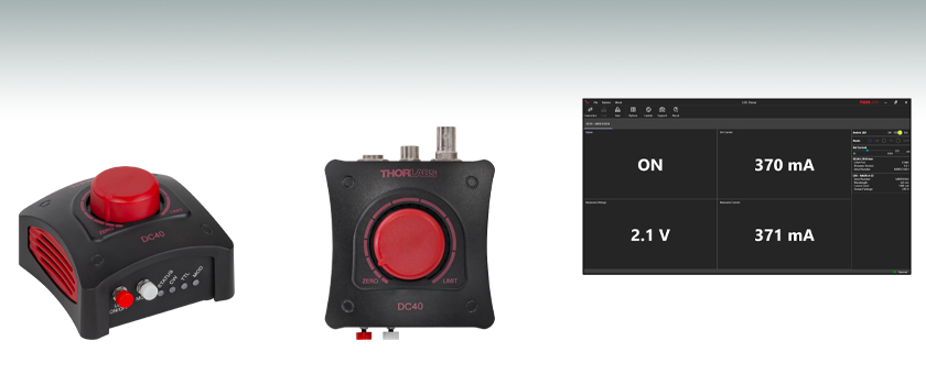
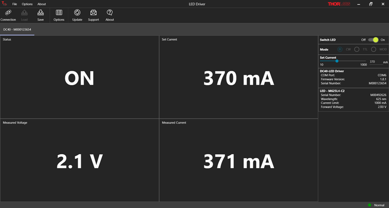
Screenshot Showing the DC40 LED Driver Software GUI While Operating With a Thorlabs LED
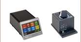
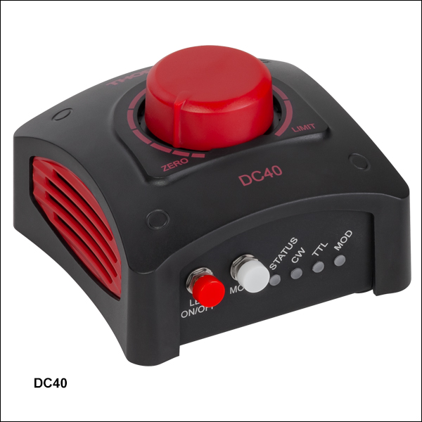
DC40
LED Driver
DC40
Top View

Please Wait
| DC40 Key Specificationsa | |
|---|---|
| LED Current (Max) | 0.1 - 4.0 A |
| LED Forward Voltage (Max)b | 14.0 V |
| LED Current Limit Accuracy | ±(1.0% + 25.0 mA) |
| TTL Modulation Frequency | DC - 5 kHz |
| External Modulation Frequency | DC - 5 kHz |
Features
- Designed for LEDs With an M8 x 1 Connector and a Maximum Drive Current Between 0.1 A and 4.0 A
- Easily Controls LED Intensity Using the Rotary Knob
- Three Operating Modes:
- Continuous Wave (CW)
- External TTL Modulation Up to 5 kHz
- Analog Modulation Up to 5 kHz
- Reads Data Stored in Thorlabs' LED EEPROM and Automatically Sets Current Limit
- Remote Control Operation via USB Interface and Software GUI
Thorlabs' DC40 LED Driver is designed to provide a simple way to control Thorlabs' LEDs with an M8 x 1 connector such as our Mounted, Collimated, Fiber Coupled, Diffuse Backlight, or Mounted PCB LEDs. This driver supports a maximum LED current between 100 mA and 4.0 A, and automatically adjusts the maximum current setting based on the information stored in the EEPROM chip, protecting the connected LED. PCB Mounted LEDs can also be driven with the DC40 driver when used with the CAB-LEDD1 LED connection cable (sold separately below). Please note that alternative LEDs can also be used, provided they meet the specifications listed on the Specs tab and either have an M8 x 1 connector or can be fitted using the CAB-LEDD1 cable (see Pin Diagrams tab).
For ease of use, the current provided to the LED can be controlled manually by turning the rotary knob on the top of the driver (see image above). The position on the top panel marked LIMIT will correspond to the maximum LED current limit for the connected LED, as the driver automatically detects and sets the current limit to the value stored when used with a Thorlabs LED with EEPROM technology. Pushing on the knob will either switch the LED on at the percentage of the maximum current indicated by the rotary knob position or turn it off. Please note that the LED can also be turned off using the LED On/Off button on the front panel.
The DC40 LED driver can drive a connected LED in three different modes: Continuous Wave (CW), Trigger (TTL), and Analog Modulation (MOD). The mode can be selected by pushing the white "MODE" button on the front panel of the driver, and the active mode is designated with a blue LED indicator. The Status LED indicates whether the device is in an active, standby, or error state and will display a green, yellow, or red light, respectively. Please see the Front & Back Panels tab for details.
A 15.0 VDC power supply with a region specific power cable cable is included with each DC40 LED driver. For a full list of items included with this driver, see the Shipping List tab.
Click to Enlarge
The main screen for the DC40 software when a Thorlabs LED with an EEPROM is in use. The screen displays the On/Off status, set current, measured current, and measured voltage. On the right side of the screen is the On/Off toggle switch, Mode selection, and set current slider.
PC Control and Software
The DC40 LED Driver can also be controlled remotely via a USB 2.0 connection on the back of the device and the downloadable Software GUI available here. When a Thorlabs LED with EEPROM technology is connected, the data will be automatically read and the current limit will be set to the maximum. The current limit can then be adjusted in the Settings section of the GUI. For LEDs without EEPROM technology and non-Thorlabs LEDs, the current limit must be set using the GUI software interface. Please note that the DC40 Software can control up to 10 LED drivers in parallel.
As shown in the image to the right, the Software GUI displays the On/Off status of the LED, and the current set point, as well as the drive current and voltage measured by the DC40 driver. The set current and current limit can only be changed in increments of 10 mA. The operating mode can also be selected through the GUI interface. Please see the Software tab or user manual for more details.
Note: If the connected LED is turned off and then back on, the set current will follow the last used interface (GUI or rotary knob). For example, If the last set current was made through the GUI, then the device will follow the GUI set value when turned on regardless of the position of the rotary knob.
Operating Modes
The CW mode is the default operating mode selected when an LED is connected to the DC40 driver. In this mode, the LED is driven with a constant current set by the rotary knob or specified in the Connection screen within the GUI.
The TTL mode operates by receiving an external-active high voltage signal through the BNC input on the back panel of the driver. A high level corresponding to a voltage of 2.6 - 5.0 V will enable the LED drive current and a low level of 0.0 - 0.8 V will switch the LED drive current off. While the input is in the high (active) state, the brightness of the LED can be controlled via the rotary knob or through the GUI. The maximum guaranteed modulation frequency for the TTL mode is 5 kHz.
The DC40 driver can also be operated in an analog modulation (MOD) mode where the output of the LED is controlled via an external voltage input through the same BNC input as the TTL signal. When operating in the MOD mode, a voltage of 0 V corresponds to 0 A drive current (the LED is off) while 5.0 V corresponds to 4.0 A drive current with a modulation coefficient of 800 mA/V. Please note that if the input voltage corresponds to a drive current above the set current limit, the supplied current will be limited to the maximum current limit.
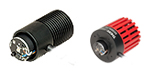
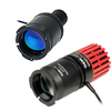
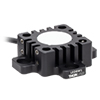
| Compatible Thorlabs LEDsa | ||
|---|---|---|
 |
 |
|
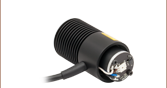
| Mounted LEDs | Collimated Microscope LEDs | |
 |
 |
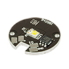 |
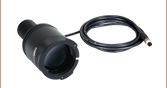
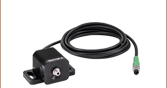
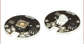
| Fiber-Coupled LEDs | Diffuse Backlight LED | PCB-Mounted LEDsb |
| LED Controller Selection Guide | ||||||
|---|---|---|---|---|---|---|
| Type | Max Number of LEDs |
Max Current |
Modulation Mode |
USB | Remote Operation | Compatible LEDs |
| upLED™ LED Driver | 1 | 1.2 A | - | Yes | Yes | Mounted, Collimated, Fiber Coupled, Diffuse Backlight, and PCB Mounteda |
| Compact T-Cube™ Driver | 1 | 1.2 A | 0 - 5 kHz | No | No | |
| 4-Channel Driver | 4 | 1 A | 0 - 100 kHz | Yes | Yes | |
| 4.0 A LED Driver | 1 | 4.0 A | 0 - 5 kHz | Yes | Yes | |
| Solis® LED Driver | 1 | 10 A | 0 - 1 kHz | No | No | High Power |
| High-Power Touchscreen Driver | 1 | 10.0 A | 0 - 250 kHz | Yes | Yes | High Power, Mounted, Collimated, Fiber Coupled, Diffuse Backlight, and PCB Mounteda |
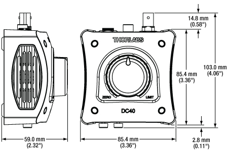
DC40 LED Driver Mechanical Dimensions
| Specificationsa | ||
|---|---|---|
| Continuous Wave (CW) Modeb | ||
| Maximum LED Currentc | 0.1 - 4.0 A | |
| Maximum LED Forward Voltagec | 14.0 V | |
| LED Current Limit Accuracy | ±(1.0% + 25.0 mA) | |
| Noise and Ripple (10 Hz to 10 MHz, RMS) | <1 mA (at 1 A over 2 Ω) | |
| TTL Modulation Moded | ||
| Input Impedance | 10 kΩ | |
| Modulation Frequency Range | DC - 5 kHz | |
| Duty Cycle Range | 0.2% - 99.8% (10 Hz) 2.0% - 98.0% (100 Hz) 25.0% - 75.0% (5 kHz) |
|
| Modulation Waveform | Square Wave Pulse Width Modulation (PWM) |
|
| TTL Voltage Level | Low | 0.0 - 0.8 V |
| High | 2.6 - 5.0 V | |
| External Modulation Moded | ||
| Input Impedance | 5 kΩ | |
| Modulation Frequency Range | DC - 5 kHz | |
| Maximum Input Voltage | 5.0 V | |
| Modulation Coefficient | 800 mA/V | |
| General Specifications | ||
| Power Supply | 15.0 VDC | |
| Maximum Power Consumption | 65 W | |
| Operating Temperature Range | 0 to 40 °C | |
| Storage Temperature Range | -40 to 70 °C | |
| Dimensions (W x H x D) | 85.4 mm x 59. 0 mm x 103.0 mm (3.36" x 2.32" x 4.06") |
|
| Weight | Without Power Supply | 230 g (0.51 lbs) |
| With Power Supply | 505 g (1.12 lbs) | |
Click for Detail
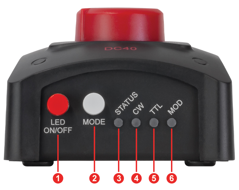
Features of the DC40 LED Driver Front Panel
Click for Detail
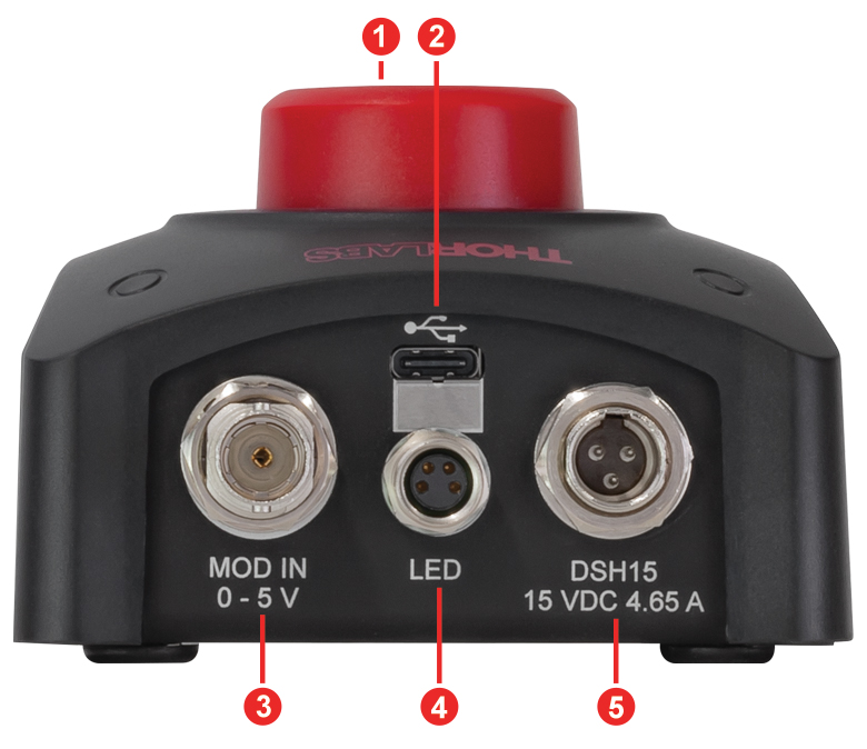
Features of the DC40 LED Driver Back Panel
| Callout | Description | |
|---|---|---|
| 1 | Push to Switch the LED On/Off | |
| 2 | Mode Selection Button | |
| 3 | Indicates the Current Status of the DC40 LED Drivera,b | |
| 4 | Indicator Light For Continuous Wave Mode | |
| 5 | Indicator Light For External TTL Trigger Mode | |
| 6 | Indicator Light For External Modulation Mode | |
| Callout | Description |
|---|---|
| 1 | Control Knob: Turn for LED Current Adjustment Push to Turn LED On and Off |
| 2 | USB 2.0 Type C Connector for Remote Operation or GUI Software Control |
| 3 | BNC Female Connector, Modulation Input for TTL and MOD Modes |
| 4 | 4-Pin M8 x 1 Female Connector For LED |
| 5 | 3-Pin, Male Mini XLR Power Supply Connector for Connecting Included 15.0 VDC Power Supply |
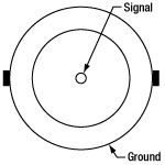
DC40 LED Driver Pin Diagrams
Modulation Input for TTL and MOD Modes
BNC Female Connector
DC40 Driver LED Terminal
M8 x 1 Female Connector

| Pin | Description |
|---|---|
| 1 | LED Anode |
| 2 | LED Cathode |
| 3 | EEPROM GNDa |
| 4 | EEPROM I/Oa |
Click to Enlarge
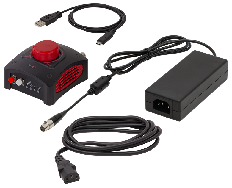
Contents in the Package of the DC40 LED Driver
The following items are included in the DC40 LED driver package.
- DC40 LED Driver
- 15.0 VDC Regulated Power Supply With Region Specific Power Cable (Labeled DSH15)
- USB Type-A to Type-C Cable
- Quick Start Reference
| Minimum System Requirements | |
|---|---|
| Operating System | Windows® 10 (32-Bit and 64-Bit), Windows® 11 |
| Processor (CPU) | 1 GHz |
| Memory (RAM) | 5012 MB |
| Hard Drive | 200 MB of Available Disk Space (64-Bit) |
| Graphics Card Resolution | 1280 x 768 |
| Interface | Free USB 2.0 Port |
Software
Software Version 1.0.0 (July 24, 2024)
Firmware Version 1.0.0 (July 24, 2024)
Click the link below to download the DC40 LED Driver Software.
Software for the DC40 4.0 A LED Driver
This software GUI for the DC40 4.0 A LED Driver allows for parallel, remote-controlled operation of up to 10 individual DC40 LED drivers. The GUI enables the user to turn on and off the LED, precisely input the current limit, adjust the set current, choose the operation mode, and save the settings for later use.
Additionally, the DC40 LED Driver and GUI will recognize when an LED with Thorlabs' EEPROM technology is connected and automatically input the current limit.
The GUI Software can be used with non-Thorlabs LEDs and Thorlabs LEDs without an EEPROM by using the toggle switch located in the Settings option of the interface and then manually setting the current limit. Please see the user manual for more details.
The available software can be downloaded by clicking on the link to the right.
| Posted Comments: | |
| No Comments Posted |

 Zoom
Zoom- LED Driver for Thorlabs and Non-Thorlabs LEDs with Maximum Drive Currents from 100 mA to 4.0 A
- Easily Turn On/Off the LED and Control Current Using the Dial
- Three Operation Modes: CW, TTL, or MOD (Analog Input) Modulation
- Available Software GUI for Remote Operation
The DC40 LED driver is a plug-and-play LED driver capable of driving both Thorlabs and non-Thorlabs LEDs with maximum drive currents from 100 mA to 4.0 A and an M8 x 1 connector. This driver can be controlled manually or remotely via the downloadable software GUI (see the Software tab for details). The rotary-push-button on the top of the device turns the connected LED on/off, as well as controls the drive current from 0 A up to the limit specified by the LED's internal EEPROM data or the current limit set in the software GUI.
An LED can be driven in three different operating modes with the DC40 driver: Continuous Wave (CW), Trigger (TTL), and Analog Modulation (MOD). Continuous Wave (CW) mode drives the LED with a constant set current, and this is the default mode when an LED is connected to the driver. The TTL mode can be used to turn the connected LED on and off using an external-active high voltage signal via the BNC input on the back panel. Similarly, the analog modulation (MOD) mode can be used to provide the LED with a user provided voltage with a modulation coefficient of 800 mA/V. In MOD mode, if the input signal sets a current higher than the output LED current limit, the driver will limit the current to the maximum current limit. Both the TTL and MOD modes can be driven at frequencies up to 5 kHz.
A 15.0 VDC power supply with a region specific power cable and a USB 2.0 Type-A to Type-C cable are included with each DC40 LED driver. For a full list of items included with this driver, see the Shipping List tab.

 Zoom
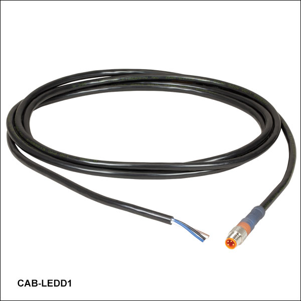
Zoom  Male M8x1 Connector |
Pin | Description | Wire Color |
|---|---|---|---|
| 1 | LED Anode | Brown | |
| 2 | LED Cathode | White | |
| 3 | EEPROM GND | Black | |
| 4 | EEPROM IO | Blue |
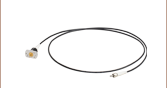
- 4-Pin M8 Connector on One Side
- 4 Bare Wires on Other Side
- 2 m Long, 24 AWG Wires
The 4-Pin M8 connection cable can be used to connect the high-power LEDs on metal core PCB or other custom LEDs to the following Thorlabs LED drivers: LEDD1B, DC40, DC2200, DC4100, and DC4104 (the latter two require the DC4100-HUB).
Pin Connection - Male
The diagram above shows the male connector for use with the above Thorlabs LED drivers. The connector is a standard M8x1 sensor circular connector. Pins 1 and 2 are the connection to the LED. If using this cable with a non-Thorlabs LED, do not connect anything to the black and blue wires, as this can damage the LED driver. Please note that the pin connection diagram shown here may not be valid for third-party LED drivers.