 Products Home
Compact Digital Servo Controller
- Digital Servo Controller with 100 kHz Bandwidth
- Servo Lock, Peak Lock, and Ramp Function Modes
- Ideal for Frequency Stabilizing Lasers
- Compact Housing with a Touchscreen Interface
Application Idea
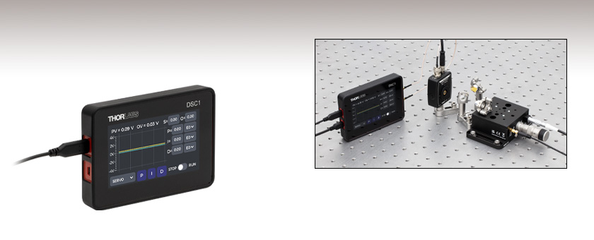
A DSC1 Compact Digital Servo Controller can be used to lock an interferometer to the peak or side of a single interference fringe by taking an input from a photodiode measuring the interferogram. The output of the DSC1 controller can then be passed to a piezo driver controlling a dynamic arm of the interferometer.
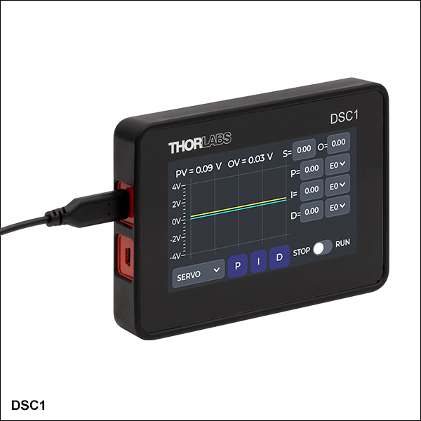
DSC1
Compact Digital Servo Controller
(Power Supply Sold Separately)


Please Wait
| Key Specificationsa | |
|---|---|
| System Bandwidth | DC to 100 kHz |
| Input-to-Output -180 Degree Frequencyb | >58 kHz (60 kHz Typical) |
| Nominal Input Sampling Resolution | 16 Bit |
| Average Noise Floor | -120 dB V2/Hz |
| Peak Noise Floor | -105 dB V2/Hz |
| Input RMS Noisec | 0.3 mV |
| Maximum Input Voltage | ±4 V |
| Maximum Output Voltaged | ±4 V |
| Dimensions (L x W x H) | 129.8 mm x 91.3 mm x 21.6 mm (5.11" x 3.59" x 0.85") |
Applications
- Single Frequency Laser or Cavity Locking
- Interferometer Stabilization
- Fourier Transform Spectroscopy
- Saturable Absorption Spectroscopy
- Dichroic Atomic Vapor Laser Locking (DAVLL)
- Active Beam-Pointing Stabilization
- Laser Power Stabilization
- Laser Repetition Rate Locking
- External Cavity Diode Lasers (ECDLs)
- Fiber Phase or Path-Length Stabilization
- Enhancement Cavity Locking for CW SHG Cavities
- Intensity Stabilization (Noise-Eating) with AOMs
- Motion Control

Click to Enlarge
The digital servo controller software provides a simple and powerful interface for the DSC1 controller. The input voltage can be displayed in either the frequency or time domain.
 The digital servo controller touchscreen interface provides full functionality in the Servo Lock, Peak Lock, and Ramp modes.
 Features
- High-Speed PID Control with up to 100 kHz Bandwidth
- Laser Lock Box Capable of Frequency Stabilizing Lasers
- Compact 130 mm Wide Enclosure Powered by USB Type-C
- Full Functionality Accessible through the Touchscreen (See the Touchscreen Tab for More Information)
- Three Modes:
- Servo Lock - Lock to a Specified Input Voltage
- Peak Lock - Dither Locking, also known as Peak Locking, Extremum Seeking Control, or Lock-In Stabilization
- Ramp - Linearly Sweep the Output Voltage Over a Defined Range
- Digital Servo Controller Software Provides Tools for Additional Analysis of Signals (See the Software Tab to Download)
- Servo Lock Mode: Displays the Input Voltage in the Time or Frequency Domain
- Peak Lock Mode: Displays the Demodulated Input Voltage in the Time or Frequency Domain
- Ramp Mode: Displays the Input Voltage as a Function of the Ramped Output Voltage like an Oscilloscope
- Can be Used to Fully Control the Digital Servo Controller
Thorlabs' DSC1 Compact Digital Servo Controller is designed to lock or stabilize an optical system to an input voltage signal by providing real-time voltage feedback determined by a user-selected control algorithm. Featuring 100 kHz of bandwidth and an input and output voltage range of ±4 V, this digital servo controller is able to actively lock with high-frequency devices like current-modulated lasers, piezo actuators, acousto-optic modulators (AOMs), electro-optic modulators (EOMs), fiber stretchers, voice coils, or fast steering mirrors.
The controller has three modes that offer complementary functionality: Servo Lock mode, Peak Lock mode, and Ramp mode.
When using the Servo Lock mode, the output voltage can be modulated with a PID (proportional, integral, derivative) algorithm to maintain a set input voltage. All the parameters of the algorithm can be tuned for the specific system. For example, the output of a system can be intensity stabilized by measuring the power with a photodiode, feeding the signal from the photodiode into the servo controller, and having the servo controller output control an intensity modulator such as an acousto-optic modulator (AOM), electro-optic modulator, or lithium niobate amplitude modulator. Changing the set point in the servo controller will cause the system to adjust to and then maintain that new set point. Additionally, the servo controller could stabilize the frequency of a laser with a side-of-fringe lock using Servo Lock mode. In a side-of-fringe lock, the set point could be placed part-way up a resonance peak from a Fabry Perot cavity or an absorption peak from an atom or molecule.
The Peak Lock mode will lock a system to a local maximum or minimum in the input voltage using dither-locking, also known as extremum seeking control or lock-in demodulation servo. It does this by modulating the system at a chosen frequency, the dither frequency, then digitally demodulating the signal to create an error function that can be minimized. By locking a system to a maximum or minimum feature in the input voltage, the performance of a system can be tightly controlled. For example, a laser can be frequency locked to a molecular absorption line in a dilute gas like acetylene or to the maximum transmission mode of a Fabry-Perot cavity with inherent immunity to drift or perturbations in laser power. See the Laser Locking tab for more information.
In the Ramp mode, the digital servo controller can linearly sweep the output voltage over a defined range and display the resultant input signal as a function of voltage, like an oscilloscope. This can resolve features like an interferogram from an interferometer as well as providing a direct view of the response of the system over an applied voltage range. For example, if the servo controller sweeps the frequency of a laser passing through a gas absorption cell, the transmission spectrum of the gas can be observed.
Application
In an application like locking an interferometer with a piezo-actuated mirror controlled by the digital servo controller, the signal from a photodiode measuring the interferogram is fed into the servo controller. When the servo controller is set in Servo Lock mode, the interferometer will be locked to an arbitrary threshold on the positive or negative slope of a single fringe in the interferogram. When the servo controller is set in Peak Lock mode, the interferometer will be locked to the peak or valley of a single fringe in the interferogram. When the servo controller is set in Ramp mode, the interferogram can be directly observed.
Touchscreen
The touchscreen interface on the DSC1 compact digital servo controller provides full functionality in all three modes. This includes running and stopping the control algorithm, changing parameters, and viewing a graph of the input voltage as a function of time. For more information, see the Touchscreen tab.
Software
The DSC1 digital servo controller can be connected to a computer for software control using the USB Type Mini-B port on the left side of the device. The user-friendly interface of the Thorlabs' Digital Servo Controller software includes controls for starting and stopping a control scheme, changing control parameters, and monitoring lock performance. It can display plots in both the time domain and frequency domain. For more information on the software, please see the Software tab.
Power
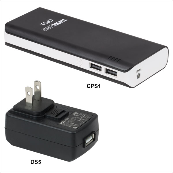
The DSC1 Digital Servo Controller is powered using the USB Type-C port on the left side of the device (see the Pin Diagrams tab). A USB Type-A to USB Type-C power cable is included (see the Shipping List tab), but power supplies are sold separately. The DS5 Regulated Power Supply or CPS1 Battery Pack is recommended for powering the DSC1 controller.
Grounding
Please note that care must be taken to avoid ground loops, which can cause irregular behavior at the measurement output for low frequencies. To avoid potentially creating paths for ground loops, the USB Type-C power port is connected to the device ground plane while the USB Type Mini-B data port floats to isolate the controller from the computer's ground. Additionally, best practices for mitigating the risk of ground loops when integrating the DSC1 controller with an experiment can be found in the manual.
Click to Enlarge
DSC1 Compact Digital Servo Controller Dimensions
| Item # | DSC1 |
|---|---|
| Operating Specifications | |
| System Bandwidth | DC to 100 kHz |
| Input to Output -180 Degree Frequencya | >58 kHz (60 kHz Typical) |
| Nominal Input Sampling Resolution | 16 Bit |
| Nominal Output Resolution | 12 Bit |
| Maximum Input Voltage | ±4 V |
| Maximum Output Voltageb | ±4 V |
| Maximum Input Current | 100 mA |
| Average Noise Floor | -120 dB V2/Hz |
| Peak Noise Floor | -105 dB V2/Hz |
| Input RMS Noisec | 0.3 mV |
| Input Sampling Frequency | 1 MHz |
| PID Update Frequencyd | 500 kHz |
| Peak Lock Modulation Frequency Range | 100 Hz - 100 kHz in 100 Hz Steps |
| Input Termination | 1 MΩ |
| Output Impedanceb | 220 Ω |
| Dimensions | 129.8 mm x 91.3 mm x 21.6 mm (5.11" x 3.59" x 0.85") |
| Electrical and Data Specifications | |
| Supply Voltage from USB | 4.75 - 5.25 V DC |
| Supply Current | 750 mA (Max) |
| Temperature Rangee | 0 °C to 70 °C |
Touchscreen
The touchscreen interface on the DSC1 Compact Digital Servo Controller provides the ability to control all parameters in each of the three modes: Servo Lock, Peak Lock, and Ramp. The output can be started and stopped with the toggle in the bottom right corner of the screen. Additionally, the plot displays the input voltage as a function of time and, in Servo Lock mode, the set-point voltage.
List of Abbreviations on the Touchscreen:
- PV - Process Variable, Volts
- This is the voltage being fed into the input of the DSC1 controller via the input SMB terminal.
- OV - Output Variable, Volts
- This is the voltage being output from the DSC1 controller via the output SMB terminal.
- S - Setpoint, Volts
- O - DC Offset, Volts
- P - Proportional Coefficient
- I - Integral Coefficient, 1/Seconds
- D - Derivative Coefficient, Seconds
- M - Modulation Frequency Multiplier, x100 Hertz (e.g., For M=5, the Modulation Frequency is 500 Hz)
- A - Amplitude, Volts
- Peak Mode: Amplitude of the Sinusoidal Modulation Voltage
- Ramp Mode: Amplitude of the Linear Voltage Ramp, from -A to +A
- K - Peak Lock Integral Coefficient
Servo Lock Mode
When the Servo Lock mode is selected, the touchscreen can be used to set all of the parameters for the servo locking function. Pressing the P, I, or D button at the bottom of the screen enables and disables their contribution to the PID calculation. Pressing the numerical values on the right of the screen allows for the coefficient value to be changed. Changing the sign of the P, I, and D coefficients switches from locking on a positive slope to a negative slope and vice versa. The setpoint and DC offset can be changed by pressing the numerical values at the top of the screen. The golden line is a display of the input voltage and the teal line is the set point.
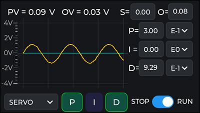 The DSC1 Compact Digital Servo Controller touchscreen interface in Servo mode.
Peak Lock Mode
When the Peak Lock mode is selected, the touchscreen can be used to set all of the parameters for the peak locking function. Pressing the numerical values on the right of the screen allows for the coefficient values of M, O, A, and K to be changed. Changing the sign of K switches from locking on a peak to a valley and vice versa. The golden line is a display of the demodulated input voltage, the error signal in the locking algorithm.
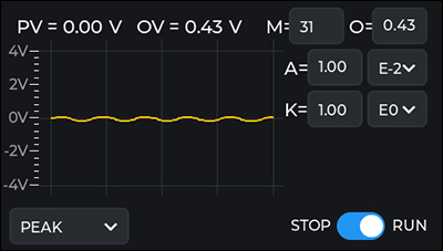 The DSC1 Compact Digital Servo Controller touchscreen interface in Peak mode.
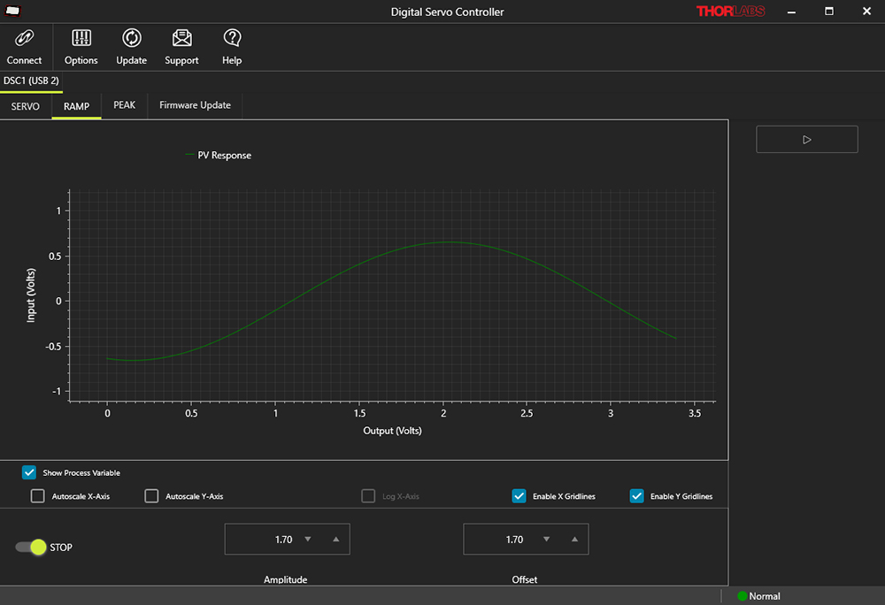
Ramp Mode
When the Ramp mode is selected, the touchscreen can be used to set all of the parameters for the ramp function. Pressing the values of O and A allows for the coefficient values to be changed. The golden line is a display of the input voltage as a function of the ramped output voltage, -3 V to 3 V in the example to the right. Note that the plot on the touchscreen interface is down-sampled and may not show fast features in the system response. These can be better seen in the computer software interface.
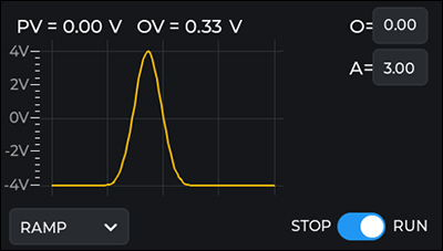 The DSC1 Compact Digital Servo Controller touchscreen interface in Ramp mode.
| Recommended System Requirements | |
|---|---|
| Operating System | Windows® 10 (Recommended) or 11, 64 Bit Required |
| Memory (RAM) | 4 GB Minimum, 8 GB Recommended |
| Storage | 300 MB (Min) of Available Disk Space |
| Screen Resolution | 1200 x 800 Pixels (Min) |
| Interface | USB 2.0 |
Software
Version 1.0.0.0 (October 21, 2024)
Click the button below to visit the Digital Servo Controller software page.

Software for the DSC1 Compact Digital Servo Controller
The digital servo controller software is designed to both allow for control over basic functionality via a computer interface and provides an expanded set of analysis tools for using the controller. For example, the GUI includes a plot that can display the input voltage in frequency domain. Additionally, data can be exported as a .csv file.
This software allows for use of the device in the servo, peak, or ramp modes with control over all parameters and settings. The system response may be viewed as the input voltage, error signal, or both, either in the time domain or frequency domain representations. Please see the manual for more information.
The Servo tab allows a user to operate the device in servo mode with additional controls and displays beyond those provided by the embedded touchscreen user interface on the device itself. On this tab, either time or frequency domain representations of the process variable are available. The system response may be viewed as either the process variable, error signal, or both. The error signal is the difference between the process variable and the setpoint. Parameters including the P, I, and D coefficients can be adjusted from this interface. Changing the sign of the P, I, and D coefficients switches from locking on a positive slope to a negative slope and vice versa.

Click to Enlarge
The digital servo controller software interface in Servo mode can control all parameters of the lock as well as display the input voltage in either the time domain or frequency domain.
The Peak tab provides the same functionality as the peak mode on the embedded user interface, with additional visibility into the nature of the return signal from the system. Switching to this tab switches the connected device to the Peak mode of operation. Parameters including A, the amplitude of the sinusoidal modulation voltage, and K, the peak lock integral coefficient, can be changed. Changing the sign of K will determine if the controller locks onto a local peak or valley in the input voltage.
Similarly to Servo Lock mode, the demodulated input voltage may be viewed in either the time domain or frequency domain.
Click to Enlarge
The digital servo controller software interface in Peak mode can control all parameters of the lock as well as display the demodulated input voltage in the time domain or frequency domain.
The Ramp tab provides comparable functionality to the ramp tab on the embedded touchscreen display. Switching to this tab puts the connected device in ramp mode.
The input signal is plotted as a function of the ramp voltage allowing for the response of the system to be monitored in the same way that an oscilloscope would be used. As the x-axis is plotted in output volts, this can be used to determine where in the voltage range a lock should be configured.
Click to Enlarge
The digital servo controller software interface in Ramp mode can control all parameters of the voltage sweep and display the response of the system as a function of voltage, alleviating the necessity for a separate oscilloscope.
Pin Diagrams for the DSC1 Digital Servo Controller
Signal Input and Output
SMB Female
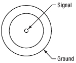
This input accepts a ±4 V voltage maximum signal with a maximum current of 100 mA. It is internally terminated with a 1 MΩ impedance. To achieve lower input impedances, a BNC feed-through terminator can be added on.
Power Input
USB Type-C
USB Type-C to Type-A Power Input Cable Included
Computer Connection
USB Type Mini-B
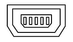
USB Type Mini-B to Type-A Data Cable Included

Click to Enlarge
DSC1 Compact Digital Servo Controller Right Panel

Click to Enlarge
DSC1 Compact Digital Servo Controller Left Panel
| Left Panel | |
|---|---|
| Call Out | Description |
| 1 | Power Input (USB Type-C) |
| 2 | Computer Connection (USB Type Mini-B) |
| Right Panel | |
|---|---|
| Call Out | Description |
| 1 | Signal Input, ±4 V (SMB Female) |
| 2 | Signal Output, ±4 V (SMB Female) |

Click to Enlarge
Components Included with the DSC1 Compact Digital Servo Controller
Components Included with the DSC1 Compact Digital Servo Controller
Laser Locking
Below are three schematic examples of how a digital servo controller could be used to frequency lock a laser.
A laser can be frequency-stabilized by locking it to an atomic or molecular absorption line. In the setup depicted to the right, a ULN15TK narrow linewidth laser is passed through a vapor reference cell filled with acetylene. A balanced photodiode (PD) measures the transmission of the laser through the acetylene cell subtracted from the intensity of the input light, generating a signal proportional to the absorption by the narrow electronic transition of the acetylene. The output from the photodiode is fed into the digital servo controller (DSC) which generates a locking signal output that is fed into the laser modulation input, causing the laser frequency to be adjusted to maintain a fixed frequency relative to the absorption peak. The digital servo controller can be used in Peak Lock mode to lock the frequency of the laser to the peak of an absorption line or in Servo Lock mode to lock to an arbitrary height on one side of the absorption line, a side-of-fringe lock like used in Thorlabs' frequency locked laser. See the Frequency Lock tab on that page for more information on frequency locking to molecular absorption lines.
A schematic diagram for frequency locking a laser to a molecular absorption line using a photodiode (PD) and a DSC1 digital servo controller.
A Fabry-Perot optical cavity can be used to frequency stabilize and narrow the linewidth of a laser using a digital servo controller. In the setup depicted to the right, a single-frequency laser is sent into a Pound-Drever-Hall (PDH) system and on into a Fabry-Perot cavity. The Pound-Drever-Hall system collects light not retained in the cavity and creates an error signal that contains a steep zero-crossing in optical frequency at the peak of a cavity transmission fringe, allowing for robust locking. The PDH error signal is then fed into the digital servo controller (DSC) running in Servo Lock mode, which in turn manipulates the modulation input of the laser diode driver to lock the frequency of the light to the maximum of the laser cavity transmission.
A schematic diagram for frequency locking a laser to an optical cavity using a Pound-Drever-Hall system and a DSC1 digital servo controller.
Transferring Stability Between Lasers Using a Fabry-Perot Cavity
A Fabry-Perot cavity (FP Cavity) can also be used as a transfer cavity lock to transfer the stability of one laser to another. In the setup depicted to the right, an atomically (or molecularly) referenced laser is fed into a Pound-Drever-Hall (PDH) system and on into a tunable Fabry-Perot cavity. The error signal from the PDH photodiode (PD) is fed into the first digital servo controller (DSC) which in turn manipulates the length of the Fabry-Perot cavity through the piezo driver (PZT Driver). This locks a cavity resonance, or fringe, to the frequency of the atomically stabilized laser. This stabilizes all the resonances of the cavity to the absorption feature used in the reference laser.
The secondary laser, which we are transferring atomically referenced stability to but can be a much different wavelength, is fed through the same Fabry-Perot cavity where a photodiode (PD) is used to measure its transmission through the PDH-stabilized cavity. The output from the photodiode is fed into the second digital servo controller (DSC) which manipulates the laser to maximize transmission through the cavity. In this example, the secondary laser frequency can be locked to the stabilized cavity using either a side-of-fringe lock or a peak lock. This locks the laser to the maximum transmission mode of the PDH-stabilized cavity, thereby transferring the frequency stability of the atomically referenced laser.
A schematic diagram for transferring stability between lasers using a Pound-Drever-Hall system, a Fabry-Perot cavity (FP Cavity) with piezo (PZT) tunability, a photodiode (PD), and two DSC1 digital servo controllers.
PID Basics
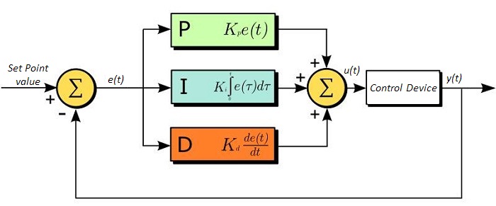
The PID circuit is often utilized as a control loop feedback controller and is commonly used for many forms of servo circuits. The letters making up the acronym PID correspond to Proportional (P), Integral (I), and Derivative (D), which represents the three control settings of a PID circuit. The purpose of any servo circuit is to hold the system at a predetermined value (set point) for long periods of time. The PID circuit actively controls the system so as to hold it at the set point by generating an error signal that is essentially the difference between the set point and the current value. The three controls relate to the time-dependent error signal. At its simplest, this can be thought of as follows: Proportional is dependent upon the present error, Integral is dependent upon the accumulation of past error, and Derivative is the prediction of future error. The results of each of the controls are then fed into a weighted sum, which then adjusts the output of the circuit, u(t). This output is fed into a control device, its value is fed back into the circuit, and the process is allowed to actively stabilize the circuit’s output to reach and hold at the set point value. The block diagram below illustrates the action of a PID circuit. One or more of the controls can be utilized in any servo circuit depending on system demand and requirement (i.e., P, I, PI, PD, or PID).
Through proper setting of the controls in a PID circuit, relatively quick response with minimal overshoot (passing the set point value) and ringing (oscillation about the set point value) can be achieved. Let’s take as an example a temperature servo, such as that for temperature stabilization of a laser diode. The PID circuit will ultimately servo the current to a Thermo Electric Cooler (TEC) (often times through control of the gate voltage on an FET). Under this example, the current is referred to as the Manipulated Variable (MV). A thermistor is used to monitor the temperature of the laser diode, and the voltage over the thermistor is used as the Process Variable (PV). The Set Point (SP) voltage is set to correspond to the desired temperature. The error signal, e(t), is then the difference between the SP and PV. A PID controller will generate the error signal and then change the MV to reach the desired result. For example, if e(t) states that the laser diode is too hot, the circuit will allow more current to flow through the TEC (proportional control). Since proportional control is proportional to e(t), it may not cool the laser diode quickly enough. In that event, the circuit will further increase the amount of current through the TEC (integral control) by looking at the previous errors and adjusting the output to reach the desired value. As the SP is reached (e(t) approaches zero), the circuit will decrease the current through the TEC in anticipation of reaching the SP (derivative control).
Please note that a PID circuit will not guarantee optimal control. Improper setting of the PID controls can cause the circuit to oscillate significantly and lead to instability in control. It is up to the user to properly adjust the PID gains to ensure proper performance.
PID Theory
The output of the PID control circuit, u(t), is given as
where
Kp= Proportional Gain
Ki = Integral Gain
Kd = Derivative Gain
e(t) = SP - PV(t)
From here we can define the control units through their mathematical definition and discuss each in a little more detail. Proportional control is proportional to the error signal; as such, it is a direct response to the error signal generated by the circuit:
Larger proportional gain results in larger changes in response to the error, and thus affects the speed at which the controller can respond to changes in the system. While a high proportional gain can cause a circuit to respond swiftly, too high a value can cause oscillations about the SP value. Too low a value and the circuit cannot efficiently respond to changes in the system.
Integral control goes a step further than proportional gain, as it is proportional to not just the magnitude of the error signal but also the duration of the error.
Integral control is highly effective at increasing the response time of a circuit along with eliminating the steady-state error associated with purely proportional control. In essence integral control sums over the previous error, which was not corrected, and then multiplies that error by Ki to produce the integral response. Thus, for even small sustained error, a large aggregated integral response can be realized. However, due to the fast response of integral control, high gain values can cause significant overshoot of the SP value and lead to oscillation and instability. Too low, and the circuit will be significantly slower in responding to changes in the system.
Derivative control attempts to reduce the overshoot and ringing potential from proportional and integral control. It determines how quickly the circuit is changing over time (by looking at the derivative of the error signal) and multiplies it by Kd to produce the derivative response.
Unlike proportional and integral control, derivative control will slow the response of the circuit. In doing so, it is able to partially compensate for the overshoot as well as damp out any oscillations caused by integral and proportional control. High gain values cause the circuit to respond very slowly and can leave one susceptible to noise and high frequency oscillation (as the circuit becomes too slow to respond quickly). Too low and the circuit is prone to overshooting the SP value. However, in some cases overshooting the SP value by any significant amount must be avoided and thus a higher derivative gain (along with lower proportional gain) can be used. The chart below explains the effects of increasing the gain of any one of the parameters independently.
| Parameter Increased | Rise Time | Overshoot | Settling Time | Steady-State Error | Stability |
|---|---|---|---|---|---|
| Kp | Decrease | Increase | Small Change | Decrease | Degrade |
| Ki | Decrease | Increase | Increase | Decrease Significantly | Degrade |
| Kd | Minor Decrease | Minor Decrease | Minor Decrease | No Effect | Improve (for small Kd) |
Tuning
In general the gains of P, I, and D will need to be adjusted by the user in order to best servo the system. While there is not a static set of rules for what the values should be for any specific system, following the general procedures should help in tuning a circuit to match one’s system and environment. A PID circuit will typically overshoot the SP value slightly and then quickly damp out to reach the SP value.
Manual tuning of the gain settings is the simplest method for setting the PID controls. However, this procedure is done actively (the PID controller turned on and properly attached to the system) and requires some amount of experience to fully integrate. To tune your PID controller manually, first the integral and derivative gains are set to zero. Increase the proportional gain until you observe oscillation in the output. Your proportional gain should then be set to roughly half this value. After the proportional gain is set, increase the integral gain until any offset is corrected for on a time scale appropriate for your system. If you increase this gain too much, you will observe significant overshoot of the SP value and instability in the circuit. Once the integral gain is set, the derivative gain can then be increased. Derivative gain will reduce overshoot and damp the system quickly to the SP value. If you increase the derivative gain too much, you will see large overshoot (due to the circuit being too slow to respond). By playing with the gain settings, you can maximize the performance of your PID circuit, resulting in a circuit that quickly responds to changes in the system and effectively damps out oscillation about the SP value.
| Control Type | Kp | Ki | Kd |
|---|---|---|---|
| P | 0.50 Ku | - | - |
| PI | 0.45 Ku | 1.2 Kp/Pu | - |
| PID | 0.60 Ku | 2 Kp/Pu | KpPu/8 |
While manual tuning can be very effective at setting a PID circuit for your specific system, it does require some amount of experience and understanding of PID circuits and response. The Ziegler-Nichols method for PID tuning offers a bit more structured guide to setting PID values. Again, you’ll want to set the integral and derivative gain to zero. Increase the proportional gain until the circuit starts to oscillate. We will call this gain level Ku. The oscillation will have a period of Pu. Gains for various control circuits are then given below in the chart.
| Posted Comments: | |
| No Comments Posted |

 Zoom
Zoom- High-Speed PID Control with up to 100 kHz Bandwidth
- Ideal for Frequency Stabilizing Lasers
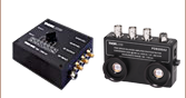
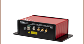
Thorlabs' DSC1 Compact Digital Servo Controller locks or stabilizes an optical system to an input voltage signal with real-time voltage feedback determined by a user-selected control algorithm. The controller has three modes that offer complementary functionality: Servo Lock mode, Peak Lock mode, and Ramp mode. The Servo Lock mode locks a system to maintain a constant specified value of the input voltage. The Peak Lock mode locks a system to a local peak or valley in the input voltage. The Ramp mode linearly sweeps the output voltage over a defined range for observation of the system's response.
The DSC1 controller includes two PAA248 SMB to BNC 48” (1.22 mm) long coaxial cables, one USB-AB-72 USB 2.0 Type-A to Mini-B 72" (1.83 m) long data cable, and one USB Type-A to USB Type-C 1 m (39") long power cable. A power supply is sold separately; the DS5 Regulated Power Supply or CPS1 Battery Pack, sold below, is recommended for powering the DSC1 controller.

 Zoom
Zoom- DS5 Power Supply Provides Power From a Wall Outlet
- CPS1 Battery Pack Allows for Lower Noise with an 8 Hour or Greater Run Time
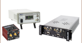
The DS5 Regulated Power Supply or CPS1 Battery Pack is recommended for powering the DSC1 controller. In applications where runtimes of greater than 8 hours are required, the DS5 regulated power supply is the preferred option. When optimal noise performance is desired, the CPS1 battery pack provides cleaner power for a lower noise floor.
DS5 Power Supply
The DS5 power supply is a 5 V, 2 A regulated power supply with a USB Type-A female port that can be used with any USB-compatible device that accepts a 5 VDC output. A region-specific adapter plug is shipped with the DS5 power supply unit based on your location.
CPS1 Battery Pack
In applications where lower noise is required, the CPS1 battery pack offers improved performance in exchange for limited run time. With the CPS1 battery pack fully charged and in good health, the DSC1 controller can operate for 8 hours or more without recharging. The CPS1 battery pack outputs 5 VDC at up to 2 A through a USB Type-A female port and offers 10 000 mAh of capacity. The pack includes a USB Type-A to Micro-B cable for charging. To activate the battery, simply push the power button once. The pack may be charged using standard 5 V USB chargers for portable devices or using a computer USB port. While the battery pack is charging, it can still supply power to an attached device.