Linear Variable Edgepass Filters
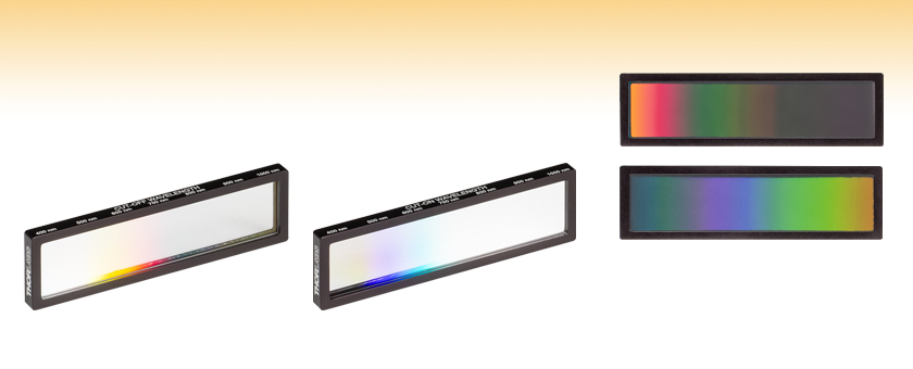
- Hard-Coated Linear Variable Shortpass and Longpass Filters
- Design Wavelength Ranges of 400 - 1000 nm or 1000 - 1700 nm
- Passband Transmission: >94%
- Out-of-Band Blocking: ODavg > 5
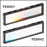
FESHV1
400 - 1000 nm
Linear Variable Shortpass Filter
FELHV1
400 - 1000 nm
Linear Variable Longpass Filter
Front View of the FELHV2 Linear Variable Longpass Filter for 1000 - 1700 nm
Front View of the FESHV2 Linear Variable Shortpass Filter for 1000 - 1700 nm

Please Wait
| Common Specifications | ||
|---|---|---|
| Out-of-Band Blockinga |
ODavg > 5, ODabs > 4 | |
| Housing Dimensions (L x H x W) |
62.9 mm x 18.0 mm x 3.9 mm (2.47" x 0.71" x 0.16") |
|
| Clear Aperture (L x H) |
58.4 mm x 13.5 mm (2.30" x 0.53") |
|
| Optic Thickness | 2.0 mm (0.08") | |
| Transmitted Wavefront Error | ≤158.2 nm RMS Over Any Ø10.0 mm Area |
|
| Surface Quality | 60-40 Scratch-Dig | |
| Parallelism | <3 arcmin | |
| Coating | Hard Coated | |
| Housing | Mounted in Black Anodized Aluminum Housing | |
| Edge Markings | Side | Item #, Engraved Arrowa |
| Top | Approximate Positions of Cut-Off or Cut-On Wavelengths | |
| Substrate | C7980c` | |
| Operating Temp | -40 °C to 150 °C | |
Click to Enlarge
Click for Raw Data
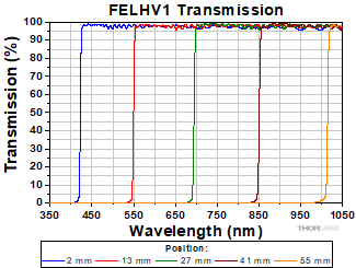
The plot above shows the transmission of a 1 mm 1/e2 diameter beam through the FELHV1 linear variable longpass filter. The positions of the beam on the filter were measured from the left inner edge of the housing when viewed in the direction of transmission.

Click to Enlarge
The top of each filter has engravings indicating the approximate location of the cut-off or cut-on wavelengths in 100 nm increments.

Click to Enlarge
The side of each filter is engraved with an arrow indicating the transmission direction.
Click to Enlarge
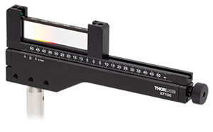
The image above shows an FESHV1 Linear Variable Filter mounted in an XF100 One-Axis Translation Mount.
Features
- Shortpass and Longpass Filters Available for Two Wavelength Ranges:
- 400 - 1000 nm
- 1000 - 1700 nm
- Suppression in Out-of-Band Regions: ODavg > 5 and ODabs > 4
- Continuously Varying Cut-Off or Cut-On Wavelength
- Rectangular Filter Clear Aperture: 13.5 mm x 58.4 mm
- Transmission Direction Engraved on Side Edge
- Relative Positions of Transmission Wavelengths Engraved on Top Edge
Thorlabs' Hard-Coated Linear, Continuously Variable Edgepass Filters are designed to provide spectral isolation with a cut-off or cut-on wavelength that varies linearly along the length of the filter. Both shortpass and longpass filters are available for wavelength ranges of 400 to 1000 nm or 1000 nm to 1700 nm. These filters offer excellent out-of-band blocking (ODavg > 5) while providing >94% transmission across entire passband. Each filter features a rectangular clear aperture and is mounted in an anodized aluminum housing. The housing is engraved with an arrow pointing towards the direction of transmission on the side edge and the approximate position of the cut-off or cut-on wavelengths in 100 nm increments (see the images above to the right). Using the filter in the orientation indicated by the engraved arrow will reduce unwanted scattering and minimize reflections sent back toward the source. These filters are ideal options to add supplementary blocking in a spectrometer or as a convenient alternative to a series of filters.
If a system with a variable bandpass is desired, a shortpass and a longpass linear variable filter can be placed in sequence to create a filter assembly with an adjustable passband width. For an example of how a filter assembly using both FESHV1 and FELHV1 linear variable filters operates, please see the Performance tab.
Variable Passband
The cut-off or cut-on wavelength of each filter varies continuously along its length. The FESHV1 and FELHV1 filters have a linear spectral gradient of 10.9 nm/mm, while the FESHV2 and FELHV2 filters have a linear spectral gradient of 12.7 nm/mm. Each filter has a cut-off or cut-on width of 9.0 nm. Please see the Specs tab for more information.
The spectral properties of these filters are specified for light normally incident on the surface. For light incident at an angle greater than 0° from normal, the transmission passband will be shifted towards shorter wavelengths. The steepness of the cut-off and cut-on transitions for each filter will decrease with increasing beam size. For light with a large beam diameter (>Ø1.0 mm) or a diverging beam, the transition will become less steep as the beam gets larger. See the Performance tab for more details on how the width of this cut-off/cut-on transition affects performance.
Mounting
These filters can be mounted in an XF100(/M) one-axis translation mount (shown above), which can be precisely translated to adjust the cut-off or cut-on wavelength.
Beam Size and Transmission
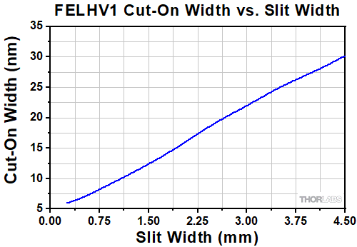
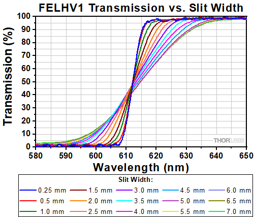
The cut-on and cut-off wavelengths of the Linear Variable Edgepass Filters are sensitive to the size of the incident beam. The plots below demonstrate the effects of the beam size on the cut-on transmission wavelength for the FELHV1 linear variable longpass filter. Data was collected by varying the size of the incident beam using an adjustable slit with widths ranging from 0.25 mm to 7.0 mm.
Click to Enlarge
Click for Raw Data
The plot above shows the cut-on width of the FELHV1 filter transmission as the input beam size is varied using an adjustable slit. This cut-on width is defined as the wavelength change required to transition from 10% to 90% transmission.
Click to Enlarge
Click for Raw Data
The plot above shows the transmission profile of the FELHV1 linear variable longpass filter as the input beam size is varied using an adjustable slit.
Angle of Incidence and Transmission
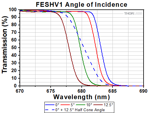
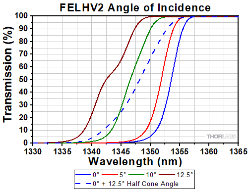
These filters are designed to operate with light normally incident on the optic (~0° AOI), but can be used with light at a non-zero angle of incidence (AOI) or with slightly diverging light. The effect of non-zero angles of incidence or an uncollimated beam are shown in the plots below. The four solid colored lines are for collimated beams with angles of incidence of 0°, 5°, 10°, and 12.5°, while the dashed line is for a beam at 0° AOI but diverging with a half-cone angle of 12.5°. All beams have a 1/e2 diameter of 1 mm at the surface of the filter. As the AOI increases, the cut-on or -off center wavelength will shift to shorter wavelengths. For a diverging or uncollimated beam at 0° AOI, the cut-on or -off width will broaden and the center wavelength will shift to shorter wavelengths.
Click to Enlarge
Click for Raw Data
The plot above shows the FESHV1 shortpass filter transmission's dependence on the AOI of the input beam. Measurements were taken using a collimated beam at four different AOIs (solid lines) and a diverging beam at 0° AOI with a half cone angle of 12.5° (dashed line). All beams had a 1 mm 1/e2 diameter at the surface of the filter.
Click to Enlarge
Click for Raw Data
The plot above shows the FELHV2 longpass filter transmission's dependence on the AOI of the input beam. Measurements were taken using a collimated beam at four different AOIs (solid lines) and a diverging beam at 0° AOI with a half cone angle of 12.5° (dashed line). All beams had a 1 mm 1/e2 diameter at the surface of the filter.
Variable Bandwidth
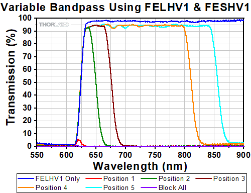
Two filters, one longpass filter and one shortpass filter, can be used to create a variable bandpass filter. The plot below shows example transmission data for a variable bandpass filter created by placing an FESHV1 linear variable shortpass filter after an FELHV1 linear variable longpass filter. The approximate positions of the FESHV1 filter relative to the position of the FELHV1 are shown in the diagram below. The FELHV1 filter is set so that the incident beam passes through it at the approximate position of the 625 nm cut-on wavelength. It is important to note that the overall transmission will decrease according to the product of the transmission percentages (0.94 x 0.94 = 0.88, or 88%).
Click to Enlarge
Click for Raw Data
The plot above shows transmission from an optical system using a combination of the FELHV1 longpass and FESHV1 shortpass linear variable filters to create a variable bandpass filter. The position of each filter relative to the incident beam can be adjusted independently, allowing for tuning of the passband.
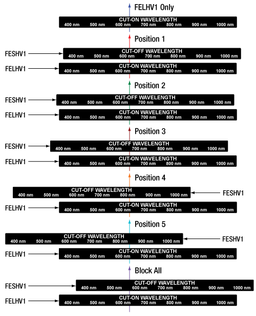
Click to Enlarge
The diagram above shows the relative positions of the FESHV1 filter relative to the position of the FELHV1 filter for the graph to the left. The colors of the arrows correspond to the color of the line shown in the plot.
| Posted Comments: | |
Max S.
(posted 2024-11-08 14:30:32.007) Good day,
what are the damage thresholds of the filters?
To use a pair of them as a variable BPF in imaging systems one has to focus the incoming radiation on the filters. And the treshold is important.
Regards cdolbashian
(posted 2024-11-27 08:45:51.0) Thank you for reaching out to us regarding this newly released product. At this time, we do not have official damage threshold tests completed, but we do have some guidelines regarding power handling. In general, you should expect damage > 1MW/cm² for CW and >= 1J/cm^2 for pulsed radiation. However, the caveat is that this only applies if the laser wavelength used is clearly in the passband or block band of the filter, and if the wavelength is in the region of the spectral edge, the values could be lower. I have contacted you directly to inquire after your light source and application. |


 Products Home


 Zoom
Zoom
 Hard-Coated Linear Variable Edgepass Filters