Kinematic Platform Positioners

- Ideal for Kinematic Stops & Reference Edges
- Allows Fine Positioning of Base Plates Prior to Lockdown
1/4"-20 (M6) Slot
(KL Positioners)
KL03
KL01
KL02L
Application Idea
A KL03L plunger provides the opposing force to a KL02 positioner. Using the KL02 adjuster, a BA2 base can move forward or backward, as indicated by the arrows.
1/4"-80
Adjustment Screw
Ball Tip Provides
One Point Contact
Spring Loaded
Plunger
APM07
3/16"-120 Fine Actuator and 1/4"-20 (M6) Taps
RSPCS
Swiveling Position Retainer

Please Wait
These kinematic positioners can be used individually or in functional groups for a variety of quick breadboard positioning and adjustment applications. The simple design and low cost make these mounts perfect alternatives for optomechanical positioning requirements when a precision translation stage is not necessary.
Insights into Best Lab Practices
Scroll down to read about a practice we follow when setting up lab equipment.
- Washers: Using Them with Optomech
Click here for more insights into lab practices and equipment.
Washers: Using Them with Optomech
Click to Enlarge
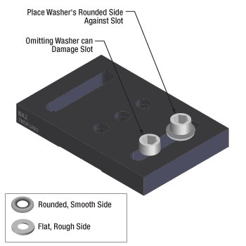
Figure 176B Install washers before inserting bolts into slots to protect the slot from damage. The rounded, smooth side of the washer should be placed against the slot, and the rough, flat side should be in contact with the bolt head. The smooth surface is designed to translate easily across the anodized surface, without harming it. The BA2 base is illustrated.
Click to Enlarge
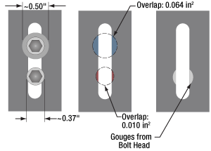
Figure 176A The diameter of the washer is 35% larger than that of the bolt head. This results in over a six fold increase in overlap area with the slot of a BA2 base. By distributing the force of the bolt over a larger area, the washer help prevent gouging of the slot.
The head of a standard cap screw is not much larger than the major diameter of the thread (Figure 176A). For example, a 1/4"-20 screw has a head diameter between 0.365" and 0.375" and the clearance hole diameter for the threads is 0.264".
When the screw is tightened directly through the clearance hole to secure the device, the force is applied to the edge of the through hole, often cutting into the material (Figure 176A).
Once the material is permanently deformed, the screw head will want to fall back into the gouged groove, thereby moving the device back to that location when attempting to make fine adjustments.
A device with a circular through hole is not meant to translate around the screw thread so the deformation is not expected to be a problem.
However, a slot should provide the ability to secure the device anywhere along the length for the lifetime of the part. Using a washer distributes the force away from the slot edge to decrease the chance of deforming the slot and extending the lifetime of the part. Figure 176A illustrates the difference a washer can make. The contact area between the slot of a BA2 base and a 0.27" diameter cap screw is 0.010 in2. When a 0.5" diameter washer is used the contact area is 0.064 in2, which is over six times larger.
When using a Thorlabs washer, there are two distinct sides (Figure 176B). One side is flat and rough and the other is curved and polished. The curved and polished side should be placed against the device, which has an anodized surface.
As the screw tightens, the screw head can force the washer to spin against the anodized coating.
If the flat side is pressed down against the anodization, the friction created by the rough flat side can scratch the anodized aluminum. However, if the curved side is facing down, the smooth surface has less friction leading to less scratches and extending the visual appearance of the device.
Date of Last Edit: Dec. 4, 2019
| Posted Comments: | |
Zachary Cadieux
(posted 2023-09-19 16:18:38.647) These are super useful, but it would be nice to have versions of these compatible with each of the different adjustment screw sizes. jdelia
(posted 2023-09-22 02:00:39.0) Thank you for contacting Thorlabs. We appreciate your feedback, and this does sounds like a good idea. I have reached out to you directly to clarify your needs and discuss your application further. tcohen
(posted 2012-06-25 08:58:00.0) Response from Tim at Thorlabs: Thank you for your interest in the KL01! The ball bearing used is Grade 440 Stainless Steel. r.jackson
(posted 2012-06-22 15:50:34.0) What is the material in the hardened ball (0.3125 dia) on the KL01 kinematic stop? |

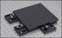
Click to Enlarge Figure G1.1 Breadboard with DF1 low-friction feet. The KL01 and KL01L kinematic stops preserve breadboard location.
- Use as a Stop or Reference Edge
- Hardened Steel Ball for One-Point Contact
- 0.74" (18.8 mm) or 1.50" (38.1 mm) Long Slot for 1/4"-20 (M6) Cap Screws
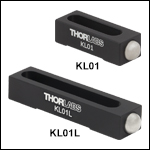
Our Fixed Kinematic Stops can be used alone, in pairs to define a reference edge, or as a group of three to define a reference edge and stop. Each stop has a hardened steel ball for a true one-point contact on one end and a base that is machined with a wide, bottom-located relief cut for stable positioning when mounting to an optical table. The KL01 is convenient to use in space constrained applications because it has a smaller slot and more compact design. The KL01L has a longer slot, capable of spanning two tapped holes at a 45 degree angle on an optical table. This allows the KL01L to be secured to a table using two cap screws, providing more stability and resistance against rotation in a system.
As shown in Figure G1.1, the fixed kinematic stops are useful in repeatable positioning when swapping a base plate or breadboard in and out of an optomechanical setup. Our kinematic stops maintain the position of an MB8 Breadboard with DF1 Low-Friction Feet. To match the height of the breadboard and low-friction feet, each stop is mounted on a BA2S6 Spacer. A KL01 and KL01L are used to define a line on one edge of the breadboard, while one KL01 acts as a stop for the perpendicular edge of the breadboard. Thus, the breadboard can be removed from its position and returned with good repeatability.

- Mark the Position of Bases within an Optical System
- Realignment Based on Three Contact Points
- Swivel Head Retainer Available with 200° of Rotation
Thorlabs' Position Retainers can be used to realign bases and other squared-off components that have been removed from an optical system. They act as markers on the breadboard or optical table in the event that you need to remove a component from your setup. The three white dots engraved on the surface of the retainer mark the three points that contact your part.
The RSPCS(/M) Swivel Retainer features a swivel head for 200° of rotational adjustment. This enables users to save the arbitrary position and angular rotation of squared-off optomechanical components. To achieve this, the component should be independently locked before aligning the three dots on the RSPCS(/M) to the corner of the component. Partially loosen the tension adjuster screw and then mount the retainer to a breadboard tap while maintaining contact with all three points. Lastly, tighten the tension adjuster screw. After this the component can be removed from the setup and then later placed back into the same position.
The RSPC Fixed Retainer is a compact solution for situations where a tapped hole is diagonally positioned from the base, as shown in Figure G2.2. As with the RSPCS, the component should be independently locked before aligning the RSPC retainer. After the retainer is mounted in place, the component can be removed from the setup and then later placed back into the same position. The RSPC Retainer can also be secured to an optical table or breadboard via the CL6 clamp. This clamp is useful in situations where the RSPC cannot be placed directly over a hole in the table.
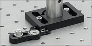
Click to Enlarge Figure G2.1 RSPCS Swiveling Position Retainer
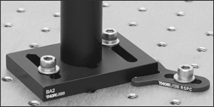
Click to Enlarge Figure G2.2 RSPC Position Retainer

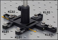
Click to Enlarge Figure G3.1 A KL03L plunger is used to provide an opposing force against the KL02 positioner, such that turning the KL02's adjuster can move the BA2 base forward or backward, as indicated by the arrows.
- High-Strength, Spring-Loaded, Plastic Plunger
- Travel Range: 0.25" (6 mm)
- 0.85" (21.6 mm) or 1.50" (38.1 mm) Long Slot for 1/4"-20 (M6) Cap Screws
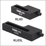
Our Spring-Loaded Plungers can be used to hold an object firmly against Kinematic Stops or an Adjustable Positioner. The high-strength plastic plunger on both the KL03 and KL03L applies spring pressure over a travel range of 0.25" (6 mm). The plunger tension can be adjusted using a 5/32" (4.0 mm) hex key. The KL03 is convenient to use in space constrained applications because it has a smaller slot and more compact design. The KL03L has a longer slot, capable of spanning two tapped holes at a 45 degree angle on an optical table. This allows the KL03L to be secured to a table using two cap screws, providing more stability and resistance against rotation in a system.
In Figure G3.1, one KL03 plunger is used with two KL01 kinematic stops while one KL03L plunger is used with a KL02 adjustable positioner to translate a BA2 base back and forth along a line. On one side of the base, two KL01 stops define a reference edge. On the opposite side, the KL03 presses the base against the two stops and prevents it from moving in the direction perpendicular to the reference edge. Along the other edges, the KL03L plunger presses against a KL02 adjustable positioner. Without the KL03L, the KL02 could only push the base forward. However, in this setup, as the KL02 is retracted, the KL03L provides an opposing force that pushes the base back.

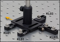
Click to Enlarge Figure G4.1 A KL02L adjustable kinematic positioner is used to finely nudge forward a BA2 base held by two KL01 kinematic stops and one KL03 plunger. The arrow indicates the direction of motion.
- Fine Control of Positioning
- Travel Range: 0.400" (10.16 mm)
- 0.85" (21.6 mm) or 1.50" (38.1 mm) Long Slot for 1/4"-20 (M6) Cap Screws
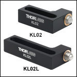
Our Adjustable Kinematic Positioners provide the same spherical contact as the Fixed Kinematic Stops presented above but adds fine adjustment capability with a 1/4"-80 actuator used as a "nudger." This feature allows for precise positioning not achievable by hand. These kinematic positioners are ideally used with two KL01 or KL01L stops to define a reference edge for a translation path. The KL02 is convenient to use in space constrained applications because it has a smaller slot and more compact design. The KL02L has a longer slot, capable of spanning two tapped holes at a 45 degree angle on an optical table. This allows the KL02L to be secured to a table using two cap screws, providing more stability and resistance against rotation in a system.
In Figure G4.1, a KL02L kinematic positioner is used to nudge a BA2 base forward along a line. The line is defined by two KL01 stops which are positioned on one side of the base. A plunger on the opposite side of the base ensures that the base stays against both fixed kinematic stops while sliding forward.


Click to Enlarge Figure G5.1 An APM05 Positioner Used with Stops to Finely Adjust a UBP2 Base Along a Straight Line
- Fine Position Control via 120 TPI Fine Hex Adjuster
- Maximum Travel Range: 0.96" (24.4 mm)
- Side-Located Counterbore for 1/4" (M6) Cap Screws Facilitates Mounting to a Breadboard or Base
- Flexure Clamp Attaches to Either End of a Ø1/2" Post
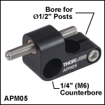
The APM05(/M) Adjustable Kinematic Positioner allows for the precise positioning of breadboards or optomechanics. It contains a high-precision 3/16"-120 hex adjuster (Item # F19MS150) that has a maximum axial load capacity of 5 lbs (2.3 kg). It can be actuated using a 5/64" (2 mm) hex key, providing fine positioning. If longer or shorter translation ranges are required, the adjuster can be replaced with any other 3/16"-120 hex adjuster.
A side-located 1/4" (M6) counterbore allows the adjuster to be attached to a breadboard, base, or to the 1/4"-20 (M6) end of a Ø1/2" post using a 1/4"-20 (M6) cap screw. In addition, it can be mounted to a Ø1/2" post using a bottom-located flexure clamp, which is tightened using a side-located cap screw and a 9/64" (3 mm) hex key. When mounted via the flexure clamp, the adjuster will be centered on top of the post. In contrast, when mounted using the side-located counterbore, the adjuster will be offset to the side by 0.40" (10.2 mm).
This adjuster can be used with any 1/4"-20 (M6) tapped optomechanics or tables, as shown in Figure G5.1. The photo shows the APM05 used in combination with two KL01 Stops and one KL03 Spring-Loaded Plunger to adjust the position of a UBP2 Universal Base Plate along a straight line.

Click to Enlarge
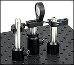
Figure G6.2 APM07 Used with a KMCP Centering Plate to Translate a Lens, with a Spring-Loaded Plunger for Counterforce
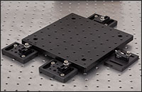
Click for Details Figure G6.1 APM07 Being Used with a BA2 Base to Translate a Breadboard, with Two KL01 Stops and One KL03 Being Used to Create a Line for Translation
Click to Enlarge
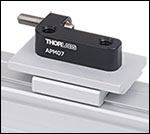
Figure G6.3 APM07 on a Rail Carrier to Finely Position Rail-Mounted Optomechanics
- Fine Position Control via 120 TPI Fine Hex Adjuster
- Maximum Travel Range: 0.66" (16.76 mm)
- Two 1/4"-20 (M6) Taps for Attachment to Bases or Ø1/2" Posts
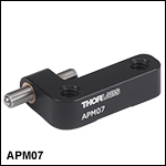
The APM07(/M) Adjustable Kinematic Positioner allows for the precise positioning of breadboards or optomechanics. It contains a high-precision 3/16"-120 hex adjuster (Item # F19MS150) that has a maximum axial load capacity of 5 lbs (2.3 kg). It can be actuated using a 5/64" (2 mm) hex key, providing fine positioning. If longer or shorter translation ranges are required, the adjuster can be replaced with any other 3/16"-120 hex adjuster. The positioner features two 1/4"-20 (M6) taps for mounting.
This adjuster can be used with optomechanics that offer 1/4"-20 (M6) taps at 1" (25 mm) spacings. Figure G6.1 shows the APM07 used in combination with two KL01 Stops and one KL03 Spring-Loaded Plunger to adjust the position of an aluminum breadboard along a straight line. Figure G6.3 shows the APM07 mounted on a 34 mm Rail using an XT34D2-50 Mounting Platform to provide positional adjustment of rail-mounted optomechanics.
Alternatively, this adjuster can be mounted on a Ø1/2" post using a 1/4"-20 (M6) cap screw or setscrew as shown in Figure G6.2. The photo shows the APM07 used with the APM06 Spring-Loaded Plunger to adjust the position of a lens mounted on the KMCP Centering Plate. The adjuster will be offset from the center of the post by 1/2" (12.7 mm) making it ideal for setups on Double Density Breadboards.
 Products Home


 Zoom
Zoom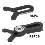
 Kinematic Stops