Cubes and Brackets for 25 mm Rails

- Construction Cubes Create Rigid Corners and Joints
- Right-Angle Brackets Provide Reinforcement and Breadboard Compatibility
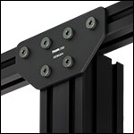
- Gusset Plates for Elbows and T-Junctions
- X- and T-Brackets for 90° Positioning
XE25GP2
Gusset Plate
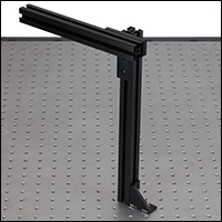
XE25A90
Right-Angle Bracket
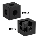
RM1G
Counterbored on
Three Sides
Application Idea
Three Rails at 90° Locked Using
XE25W3 Cube
RM1S
Slotted to Accept Hardboard
XET1
Large T-Bracket for
25 mm Rails

Please Wait
| XE25 25 mm Construction Rail Accessories | ||||
|---|---|---|---|---|
 |
 |
 |
 |
 |
| Rails | Cubes and Brackets |
Breadboard Mounting |
Rail Joiners | Channel Insert |
 |
 |
 |
 |
|
| Construction Tools |
T-Nuts and Screws |
Enclosures | Enclosure Accessories |
|
Features
- High-Strength Plastic or Aluminum Cubes Form Rigid Connections Between 25 mm Rails
- Right-Angle Brackets Reinforce Corners and Fasten Rails to Breadboards and Optical Tables
- Gusset Plates Reinforce Elbows and Three-Way Junctions
- X and T-Shaped Brackets Align Rails at 90°
The Cubes, Brackets, and Gusset Plates below are designed to allow our 25 mm rails to be used in two or three dimensional right-angle constructions.
Construction Cubes
Our construction cubes create rigid corners in 25 mm rail assemblies, holding up to three XE25 rails at right angles. The RM1G and RM1S Counterbored Construction Cubes are manufactured from anodized aluminum, while the XE25W3 Quick Corner Cube is fabricated from high-strength plastic. The aluminum RM1S cube is slotted to accept posterboard and hardboard walls for the construction of light-tight optical enclosures.
Right-Angle Brackets
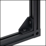
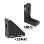
The AB90H and XE25A90 Right-Angle Brackets can be used to fasten 25 mm rails at 90° or a single 25 mm rail at 90° to a breadboard.
Gusset Plates
Our gusset plates mount 25 mm rails at 90° with other 25 mm, 50 mm, or 75 mm rails in elbow or tee configurations without blocking the rail channels along the inner surfaces of the junction.
X- and T-Brackets
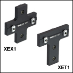
The XEX1 X-Shaped Bracket or XET1 T-Shaped Bracket can be used to connect two 25 mm rails at 90° to each other.
Thorlabs' accessories for assemblies made of 25 mm rails include corner cubes and brackets, T-Nuts, low-profile channel screws, breadboard mounting accessories, rail joiners, and a channel insert. In addition, we offer optical enclosures, enclosure accessories, laser safety fabric panels, and do-it-yourself tools like taps, tap guides, and drill guides for home-built XE25-based constructions.

Click to Enlarge
Home-Built 90° Corner
XE25 Construction Techniques
Thorlabs' XE25 rails and components are the building blocks for many types of modular systems, including custom enclosures. For the most demanding applications, Thorlabs recommends the "direct connection" technique for forming right angles with rails, detailed here. All the construction parts shown in this tutorial are available on our XE25 Construction Tools page.
Step 1: Drill Side Holes
A Ø4.6 mm hole in the end of one rail, as shown in the picture to the right, is needed to provide access for a 1/8" (4 mm) balldriver.
For this step, you will need the T119873 Ø4.6 mm Drill Bit, the XE25DG Drill Guide, a hand drill or drill press, and a vise.
The XE25DG drill guide is secured to the rail using the locking screw on top. A guide hole for the drill bit will be located 12.5 mm from the end of the rail. Now a hole can be drilled into the rail as shown in the figure to the left.
If your application requires a "three-way corner," such as that shown at the top of the page, you will have to drill a second hole in the rail at a 90° angle relative to the first hole.
Step 2: Tap the Center Hole, If Necessary
All stock and custom-length anodized XE25 rails have a 1/4"-20 (M6) tapped hole in the end of the rail. If you have cut a standard XE25 rail, or are using the XE25RL2 Raw Extrusion, you will need to tap a hole into the end of the rail.
For this step, you will need the 71598 1/4"-20 Tap (or the 71498 M6 Tap), the XE25TG Tap Guide, and the TW25 Hand Tap Wrench.
Fix the tap inside the tap wrench. Place the tap guide block over the end of the rail. The hole in the top of the guide will keep the tap square with the hole and minimize the chance of misthreading. Turn the tap to thread the hole.
Step 3: Attach Low-Profile Channel Screw
For this step, you will need a SH25LP38 1/4"-20-threaded (SH6M10LP M6-threaded) Low-Profile Channel Screw and a 1/8" (4 mm) balldriver.
Insert the screw into the threaded hole in the end of the rail, and tighten down partway with the balldriver. If you are making a three-way connection, you will need to thread another channel screw into the end of a second rail.
Step 4: Join the Rails
Slide the head of the channel screw into the channel of the rail with the drilled holes, so that the hex head lines up with the hole. Insert the balldriver into the hole, and tighten the channel screw. If making a three-way connection, repeat this process with the third rail, as shown in the figure to the right.
For increased stability, the corners may be reinforced with the XE25A90 Right-Angle Bracket.
| Posted Comments: | |
Iain Robinson
(posted 2020-08-11 15:14:03.167) Could you have a look at the drawing of RM1G? It shows that the cube is a 25 mm square. I believe this should be 25.4 mm. nbayconich
(posted 2020-08-18 04:16:21.0) Thank you for your feedback. We will update the drawings accordingly. bdada
(posted 2012-02-24 09:48:00.0) Response from Buki at Thorlabs:
We would like to contact you to verify the components you have received and send you replacements if necessary. Please email us at techsupport@thorlabs.com so we can assist you further. tcohen
(posted 2012-02-22 10:00:00.0) Response from Tim at Thorlabs: Thank you for your feedback. The 1/4”-20 stainless steel socket head cap screw packaged with the XE25LS is 1.25”. We don’t have your email to contact you, but if you feel that the wrong SHCS was packaged with your XE25LS please contact us at techsupport@thorlabs.com and we would be more than happy to provide you with the correct screw. user
(posted 2012-02-21 19:02:52.0) The SHCS that comes with the XE25LS is 1", which is the same as the RM1G Corner Cube which is needs to span, hence the screw can't engage the threads. |

Click to Enlarge
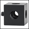
Low-Profile Screw in RM1G Construction Cube
Click to Enlarge
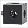
Standard Cap Screw in RM1G Construction Cube
Click to Enlarge
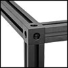
Three-Way 25 mm Rail Junction Using an RM1G Construction Cube
Click to Enlarge
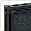
RM1S Slotted Cube Securing a Hardboard Enclosure Wall
- RM1G: Counterbored on Three Sides
- RM1S: Counterbored on Three Sides and Slotted to Accommodate Panels
- One-Piece Aluminum Construction for Excellent Rigidity
- Parallel and Perpendicular to Within 0.002" (0.05 mm)
These Construction Cubes contain three 1/4" (M6) counterbores on adjacent faces. They can be connected to up to three rails by tightening our low-profile channel screws (sold separately) through the counterbores, as shown in the first two images to the right. The third and fourth images illustrate how a low-profile screw's shortened cap height prevents neighboring screws from interfering with each other. In addition, the RM1S cube has slotted corners to accept posterboard and hardboard walls for the construction of light-tight optical enclosures. Since both these cubes are machined from a single block of aluminum, they are ideal for constructions that need to be as sturdy as possible.

Click to Enlarge
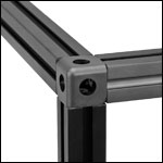
Three-Way 25 mm Rail Junction Using an XE25W3 Quick Corner Cube
- Holds up to Three Rails at Right Angles
- Made from High-Strength Reinforced Plastic
- For Use with Low-Profile Channel Screws
The prongs on the faces of an XE25W3 Quick Corner Cube are positioned to fit into the four alignment holes on the end of a 25 mm rail. Because the prongs and the alignment holes form a tight fit, it may be difficult to insert the corner cube by hand. We therefore recommend using our low-profile channel screws (sold separately) to fasten the corner cube to the rail, as shown in the image and the animation to the right.
Although these corner cubes provide excellent results when building enclosures, they are not recommended in cases where rails are being used to support optomechanics. In these situations, please use the RM1G Construction Cube shown above, or consider the techniques shown in the Construction Methods tab.

Click to Enlarge
Reinforced Corner
Click to Enlarge
Enclosure Bolted to Optical Table
- Brace 25 mm Rail Corners or Mount Rails Vertically
- One-Piece Aluminum Construction for Excellent Rigidity
- For Use with 1/4"-20 (M6) Cap Screws
The AB90H and XE25A90 Right-Angle Brackets can be used to fasten 25 mm rails to each other using a T-Nut (sold separately) or to an optical table. Both intended for use with 1/4"-20 (M6) cap screws and washers, the AB90H has a total of two 1/4" wide slots of lengths of 1" (25.4 mm) and 0.5" (12.7 mm), allowing for additional flexibility in positioning the rails on a breadboard, while the XE25A90 has two counterbored holes.
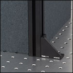
These brackets are ideal for fastening our optical enclosures to an optical table or breadboard.

Click to Enlarge
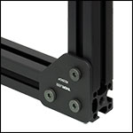
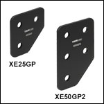
XE25GP Gusset Plate Connecting Two 25 mm Rails
| Item # | Rail 1 | Rail 2 | Recommended # of Nut & Screw Setsa |
|---|---|---|---|
| XE25GP | 25 mm | 25 mm | 3 |
| XE50GP2 | 50 mm | 5 | |
| XE75GP2 | 75 mm | 7 |
- Connect Two Rails at a 90° Elbow
- 1/8" (3.2 mm) Thick Anodized Aluminum
- For Use with Low-Profile 1/4"-20 (M6 x 1.0) Channel Screws and
T-Nuts (Sold Separately; See Table to the Right for Details)
These gusset plates are used to create strong 90° elbows using our 25 mm, 50 mm, and 75 mm construction rails. They provide reinforcement similar to the right-angle brackets sold above but do not block the inner channels of the elbow joint, instead leaving them open for hardboard or plexiglass panels. Each gusset plate features mounting holes designed for use with low-profile 1/4"-20 (M6 x 1.0) channel screws (10 mm max length) and matched T-nuts (both sold separately). When attaching rails of different sizes, we recommend mounting the smaller rail using multiple holes along the base of the gusset plate to provide additional rigidity, if possible.
To assemble, insert the screws into the gusset plate and loosely thread them into nuts on the back. Then slide the nuts into the rail channels and align the rail ends. With the rails aligned, tighten the channel screws.

Click to Enlarge
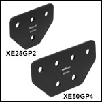
XE50GP4 Gusset Plate Connecting a 25 mm Rail to a 50 mm Rail
| Item # | End Rail(s) |
Center Rail |
Recommended # of Nut & Screw Setsa |
|---|---|---|---|
| XE25GP2 | 25 mm | 25 mm | 4 |
| XE50GP4 | 50 mm | 6 | |
| XE75GP5 | 75 mm | 8 |
- Connect Two or Three Rails in a Three-Way Junction
- 1/8" (3.2 mm) Thick Anodized Aluminum
- For Use with Low-Profile 1/4"-20 (M6 x 1.0) Channel Screws and
T-Nuts (Sold Separately; See Table to the Right for Details)
These gusset plates are used to create strong three-way junctions using our 25 mm, 50 mm, or 75 mm construction rails. They provide reinforcement similar to the elbow gusset plates sold above but with additional mounting holes to form a tee. Each gusset plate features mounting holes designed for use with low-profile 1/4"-20 (M6 x 1.0) channel screws (10 mm max length) and matched T-nuts (both sold separately). When attaching rails of different sizes, we recommend mounting the smaller rail using multiple holes along the base of the gusset plate to provide additional rigidity, if possible.
To assemble, insert the screws into the gusset plate and loosely thread them into nuts on the back. Then slide the nuts into the rail channels and align the rail ends. With the rails aligned, tighten the channel screws.

Click to Enlarge
A T-shaped bracket secures two 25 mm rails at 90°.
- Secure Two 25 mm Rails in a 90° Alignment
- Raised Guides Fit in Rail Channels for Quick Alignment
- X and T Shapes for Precise Positioning
Thorlabs' X- and T-Shaped Brackets allow 25 mm Optical Rails to be connected in 90° orientations.
Each bracket comes with four pre-installed M4 screws and T-nuts. To mount a bracket on an XE25 series rails, first loosen the attached T-nuts until they can rotate freely. Then, insert the T-nuts on one side of the bracket into one of the rail channels. Ensure the T-nuts are rotated so that they will engage with the rail channels and the raised section of the bracket is sitting in the channel to ensure proper alignment. Tighten the M4 screws with a 1/8" (3 mm) hex key or ball driver to secure the bracket in place. Once the bracket is secured to the first rail, the procedure can be repeated for the second rail, using the raised section on the opposite face to align the second rail at 90° to the first.
The X-bracket can be used to position two rails perpendicularly along their length, while the T-bracket's design allows it to be used to position one rail perpendicularly at the end of a second rail, without the bracket extending beyond the setup.
The XEX1L and XET1L X- and T-shaped brackets provide additional compatibility with our 50 mm and 75 mm rails.
 Products Home


 Zoom
Zoom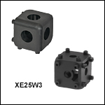
 25 mm Cubes and Brackets