T-Cube™ TEC Controller
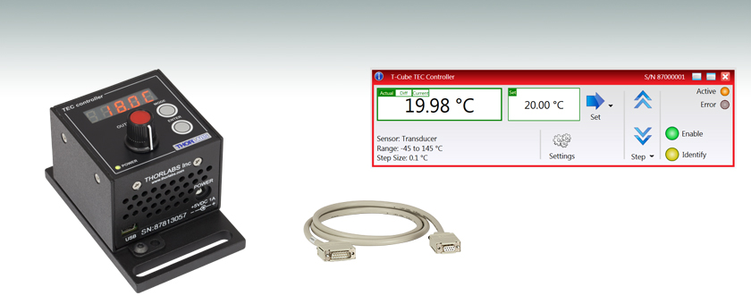
- Microcontroller-Based PID Temperature Controller
- ±1 A and 4 W TEC Output
- USB Plug-and-Play with Full Software Control Suite
TTC001
Power Supply
and TEC Cable
Included
CAB420-15
Kinesis® Software Included

Please Wait
Click to Enlarge
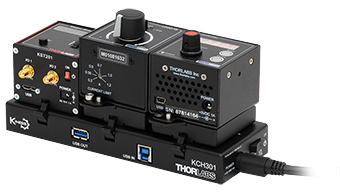
KCH301 USB Controller Hub with Installed T-Cube and K-Cube™ Modules
Click to Enlarge
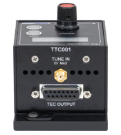
Back View of the TTC001 T-Cube (See the Pin Diagrams Tab for More Information)
Features
- Compact T-Cube Footprint
- ±1 Amp/4 W TEC Output
- Microcontroller-Based PID Temperature Control
- 5-Digit LED Display
- Display Modes Include Temperature and TEC Current
- Temperature and Current Limit Set Points
- Compatible with Thermistor AD590 and AD592 Sensors
- Remote Control via USB; Local Control via Buttons and Adjustment Pot
- Monitor Output Connection; Analog Control Input Connection
The TTC001 T-Cube TEC Controller is designed for high-precision thermal control of small temperature sensitive components. It is designed to drive an external Peltier effect thermoelectric heater/cooler coupled to a standard thermistor or IC sensor. The highly precise, closed-loop control is suitable for many applications.
The various parameters, such as temperature set point, current limit, temperature sensor type, and PID parameters, are adjustable from the front panel interface for quick and easy local control. The unit can be interfaced to a PC using a USB cable and all of the parameters can be set using the included software. The unit is equipped with a 5-digit, 7-segment illuminated display. The user-selectable display modes can be set to show actual temperature, set point temperature, TEC current, and TEC current limit. The bipolar output stage allows both cooling and heating with currents up to 1 A. The TEC T-Cube is compatible with the LM14S2 and our High-Power Laser Mounts in addition to the Thorlabs' TEC3-2.5 - TH10K combination (TEC element - thermistor respectively).
The TTC001 may be mounted directly onto an optical table and operated as a stand-alone unit with the included 5 V power supply. Included with the unit is the Kinesis® software package, which allows quick setup and control of the TTC001 and is the same software used to control all of our other T-Cube and K-Cube products. The Kinesis software features .NET controls that can be used by third-party developers working in compatible languages such as C, C# and LabVIEW™ to create custom applications
Connection Cables
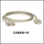
A CAB420-15 is required to connect the TTC001 T-Cube TEC Controller to a Thorlabs' Laser Diode Mount. This cable is included with the TTC001 and has a length of 1.5 m. Additional cables can be ordered below.
| Item # | TTC001 | |||
|---|---|---|---|---|
| Temperature Sensor | ||||
| Type of Sensor | Thermistor 20 kΩ | Thermistor 200 kΩ | AD590 | AD592 |
| Thermistor Sensing Current | 100 µA | 10 µA | - | - |
| Control Range | 10 Ω to 20.000 kΩ | 100 Ω to 200.00 kΩ | -45 to 125 °C | |
| Setting Measurement Resolution | 10 Ω | 100 Ω | 0.1 °C | |
| Accuracy (5%) | ±100 Ω | ±1 kΩ | ±1 °C | |
| Temperature Stability, 24 Hours | 5 Ω | 50 Ω | < 0.5 °C | |
| TEC Output | ||||
| Control Range of the TEC Current | ±1 A | |||
| Measurement Resolution TEC Current | 1 mA | |||
| Accuracy TEC Current | ±20 mA | |||
| Output Voltage (Max) | 4 V | |||
| Output Power (Max) | 4 W | |||
| Noise and Ripple (Typical) | < 1 mA | |||
| TEC Current Limit | ||||
| Setting Range | 100 mA to 1 A | |||
| Measurement Resolution | 10 mA | |||
| Accuracy | ±1 mA | |||
| Temperature Control Input (TUNE IN) | ||||
| Input Resistance | 2.5 kΩ | |||
| Control Voltage | 0 to 5 V | |||
| General Data | ||||
| Warm Up Time | 10 Minutes for Maximum Accuracy | |||
| Power Supply | 5 VDC, 2.1 mm Jack Connection | |||
| Housing Dimensions (W x D x H) | 60 mm x 60 mm x 47 mm (2.4" x 2.4" x 1.8") | |||
| Weight | 160 g (5.5 oz) | |||
TEC Output
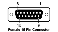
| Pin | Connection | Pin | Connection |
|---|---|---|---|
| 1 | Not Connected | 9 | Not Connected |
| 2 | Not Connected | 10 | Transducer AD592 (-ve) |
| 3 | Thermistor -ve, Ground | 11 | Transducer AD592 (+ve) |
| 4 | Thermistor +ve | 12 | Not Connected |
| 5 | TEC (+) | 13 | TEC (-) |
| 6 | TEC (+) | 14 | TEC (-) |
| 7 | TEC (+) | 15 | TEC (-) |
| 8 | Not Connected |
Tune In

Used to control the output of the controller from an external source. A zero to 5 V analog input can be used to either adjust the set temperature, allowing the PID loop to maintain the desired temperature, or it can be used to directly control the current output of the controller.
Computer Connection*

*USB type Mini-B to type A cable included.
T-Cube Mounting Options
Two options are available to securely mount our T-Cube controllers onto an optical table. An optical table mounting plate, provided with every T-Cube, allows for a single controller to be attached to an optical table. Alternatively, multiple units can be mounted and connected to a single PC by using the KCH301 or KCH601 USB Controller Hubs. They each consist of two parts: the hub, which can support up to three (KCH301) or six (KCH601) T-Cubes or K-Cubes, and a power supply that plugs into a standard wall outlet. Current- and previous-generation T-Cubes require the previously mentioned mounting plate to be removed and replaced with the KAP101 Adapter Plate, shown in the animation below.
T-Cube and K-Cube Mounting On USB Controller Hubs
3- and 6-Port USB Controller Hubs allow multiple controllers to be connected to one PC for multi-axis applications. K-Cubes can be directly attached to the hubs while T-Cubes require a KAP101 Adapter Plate.
PID Basics
The PID circuit is often utilized as a control loop feedback controller and is commonly used for many forms of servo circuits. The letters making up the acronym PID correspond to Proportional (P), Integral (I), and Derivative (D), which represents the three control settings of a PID circuit. The purpose of any servo circuit is to hold the system at a predetermined value (set point) for long periods of time. The PID circuit actively controls the system so as to hold it at the set point by generating an error signal that is essentially the difference between the set point and the current value. The three controls relate to the time-dependent error signal. At its simplest, this can be thought of as follows: Proportional is dependent upon the present error, Integral is dependent upon the accumulation of past error, and Derivative is the prediction of future error. The results of each of the controls are then fed into a weighted sum, which then adjusts the output of the circuit, u(t). This output is fed into a control device, its value is fed back into the circuit, and the process is allowed to actively stabilize the circuit’s output to reach and hold at the set point value. The block diagram below illustrates the action of a PID circuit. One or more of the controls can be utilized in any servo circuit depending on system demand and requirement (i.e., P, I, PI, PD, or PID).
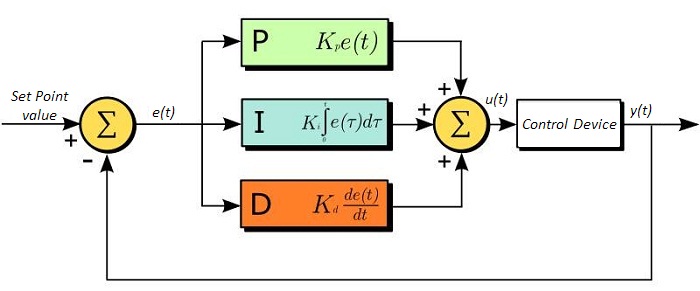
Through proper setting of the controls in a PID circuit, relatively quick response with minimal overshoot (passing the set point value) and ringing (oscillation about the set point value) can be achieved. Let’s take as an example a temperature servo, such as that for temperature stabilization of a laser diode. The PID circuit will ultimately servo the current to a Thermoelectric Cooler (TEC) (often times through control of the gate voltage on an FET). Under this example, the current is referred to as the Manipulated Variable (MV). A thermistor is used to monitor the temperature of the laser diode, and the voltage over the thermistor is used as the Process Variable (PV). The Set Point (SP) voltage is set to correspond to the desired temperature. The error signal, e(t), is then the difference between the SP and PV. A PID controller will generate the error signal and then change the MV to reach the desired result. For example, if e(t) states that the laser diode is too hot, the circuit will allow more current to flow through the TEC (proportional control). Since proportional control is proportional to e(t), it may not cool the laser diode quickly enough. In that event, the circuit will further increase the amount of current through the TEC (integral control) by looking at the previous errors and adjusting the output to reach the desired value. As the SP is reached (e(t) approaches zero), the circuit will decrease the current through the TEC in anticipation of reaching the SP (derivative control).
Please note that a PID circuit will not guarantee optimal control. Improper setting of the PID controls can cause the circuit to oscillate significantly and lead to instability in control. It is up to the user to properly adjust the PID gains to ensure proper performance.
PID Theory
The output of the PID control circuit, u(t), is given as

where
Kp= Proportional Gain
Ki = Integral Gain
Kd = Derivative Gain
e(t) = SP - PV(t)
From here we can define the control units through their mathematical definition and discuss each in a little more detail. Proportional control is proportional to the error signal; as such, it is a direct response to the error signal generated by the circuit:

Larger proportional gain results in larger changes in response to the error, and thus affects the speed at which the controller can respond to changes in the system. While a high proportional gain can cause a circuit to respond swiftly, too high a value can cause oscillations about the SP value. Too low a value and the circuit cannot efficiently respond to changes in the system.
Integral control goes a step further than proportional gain, as it is proportional to not just the magnitude of the error signal but also the duration of the error.

Integral control is highly effective at increasing the response time of a circuit along with eliminating the steady-state error associated with purely proportional control. In essence integral control sums over the previous error, which was not corrected, and then multiplies that error by Ki to produce the integral response. Thus, for even small sustained error, a large aggregated integral response can be realized. However, due to the fast response of integral control, high gain values can cause significant overshoot of the SP value and lead to oscillation and instability. Too low, and the circuit will be significantly slower in responding to changes in the system.
Derivative control attempts to reduce the overshoot and ringing potential from proportional and integral control. It determines how quickly the circuit is changing over time (by looking at the derivative of the error signal) and multiplies it by Kd to produce the derivative response.

Unlike proportional and integral control, derivative control will slow the response of the circuit. In doing so, it is able to partially compensate for the overshoot as well as damp out any oscillations caused by integral and proportional control. High gain values cause the circuit to respond very slowly and can leave one susceptible to noise and high frequency oscillation (as the circuit becomes too slow to respond quickly). Too low and the circuit is prone to overshooting the SP value. However, in some cases overshooting the SP value by any significant amount must be avoided and thus a higher derivative gain (along with lower proportional gain) can be used. The chart below explains the effects of increasing the gain of any one of the parameters independently.
| Parameter Increased | Rise Time | Overshoot | Settling Time | Steady-State Error | Stability |
|---|---|---|---|---|---|
| Kp | Decrease | Increase | Small Change | Decrease | Degrade |
| Ki | Decrease | Increase | Increase | Decrease Significantly | Degrade |
| Kd | Minor Decrease | Minor Decrease | Minor Decrease | No Effect | Improve (for small Kd) |
Tuning
In general the gains of P, I, and D will need to be adjusted by the user in order to best servo the system. While there is not a static set of rules for what the values should be for any specific system, following the general procedures should help in tuning a circuit to match one’s system and environment. A PID circuit will typically overshoot the SP value slightly and then quickly damp out to reach the SP value.
Manual tuning of the gain settings is the simplest method for setting the PID controls. However, this procedure is done actively (the PID controller turned on and properly attached to the system) and requires some amount of experience to fully integrate. To tune your PID controller manually, first the integral and derivative gains are set to zero. Increase the proportional gain until you observe oscillation in the output. Your proportional gain should then be set to roughly half this value. After the proportional gain is set, increase the integral gain until any offset is corrected for on a time scale appropriate for your system. If you increase this gain too much, you will observe significant overshoot of the SP value and instability in the circuit. Once the integral gain is set, the derivative gain can then be increased. Derivative gain will reduce overshoot and damp the system quickly to the SP value. If you increase the derivative gain too much, you will see large overshoot (due to the circuit being too slow to respond). By playing with the gain settings, you can maximize the performance of your PID circuit, resulting in a circuit that quickly responds to changes in the system and effectively damps out oscillation about the SP value.
| Control Type | Kp | Ki | Kd |
|---|---|---|---|
| P | 0.50 Ku | - | - |
| PI | 0.45 Ku | 1.2 Kp/Pu | - |
| PID | 0.60 Ku | 2 Kp/Pu | KpPu/8 |
While manual tuning can be very effective at setting a PID circuit for your specific system, it does require some amount of experience and understanding of PID circuits and response. The Ziegler-Nichols method for PID tuning offers a bit more structured guide to setting PID values. Again, you’ll want to set the integral and derivative gain to zero. Increase the proportional gain until the circuit starts to oscillate. We will call this gain level Ku. The oscillation will have a period of Pu. Gains for various control circuits are then given to the right in the chart.
Note that when using the Ziegler-Nichols tuning method with some devices like the DSC1 digital servo controller, the integral and derivative terms must be normalized by the sample rate. To do this, the integral term determined from the table should be divided by the sample rate in Hertz and the derivative term should be multiplied by the sample rate in Hertz.
Software
Kinesis Version 1.14.50
The Kinesis Software Package, which includes a GUI for control of Thorlabs' Kinesis system controllers.
Also Available:
- Communications Protocol

Kinesis GUI Screen
Thorlabs offers the Kinesis® software package to drive our wide range of motion controllers. The software can be used to control devices in the Kinesis family, which covers a wide variety of motion controllers ranging from small, low-powered, single-channel drivers (such as the K-Cubes™) to high-power, multi-channel benchtop units and modular 19" rack nanopositioning systems (the MMR60x Rack System).
The Kinesis Software features .NET controls which can be used by 3rd party developers working in the latest C#, Visual Basic, LabVIEW™, or any .NET compatible languages to create custom applications. Low-level DLL libraries are included for applications not expected to use the .NET framework and APIs are included with each install. A Central Sequence Manager supports integration and synchronization of all Thorlabs motion control hardware.
By providing this common software platform, Thorlabs has ensured that users can mix and match any of our motion control devices in a single application, while only having to learn a single set of software tools. In this way, it is perfectly feasible to combine any of the controllers from single-axis to multi-axis systems and control all from a single, PC-based unified software interface.
The software package allows two methods of usage: graphical user interface (GUI) utilities for direct interaction with and control of the controllers 'out of the box', and a set of programming interfaces that allow custom-integrated positioning and alignment solutions to be easily programmed in the development language of choice.
Legacy Software
Select products are still capable of running the legacy APT™ software package. Information on software compatibility can be found in the product documentation (![]() ), and additional details about the APT software can be found here.
), and additional details about the APT software can be found here.
| Posted Comments: | |
Hongtu Pu
(posted 2023-05-22 11:46:07.21) We are interested in your thermal controller TTC001 and have a question. below.
Can we set a temperature cycle with this controller?
e.g. from 20C to 70C in 1~2 Hz. Any suggestion of TEC and thermistor?
Thanks,
Hongtu cdolbashian
(posted 2023-05-26 02:27:28.0) Thank you for reaching out to us with this inquiry. The choice of a TEC and thermistor depends on the application and material being heated/cooled. A sequence such as you described can be accomplished fairly easily within our Kinesis software, by creating a suitable loop using our Sequencer feature. The email provided was unable to deliver, so I hope you see this response here. If you have further inquiries, please contact techsupport@thorlabs.com Mattias Melin
(posted 2022-10-03 08:48:48.52) Hello, is it possible to control HLD001 with this TTC001? I see there are pins avaible to read Thermistor and to feed cooler. Do you have any cabling that support this? ksosnowski
(posted 2022-10-07 01:51:49.0) Thanks for reaching out to Thorlabs. Unfortunately, we do not offer a cable for the HLD001, though a spare DB9 cable from the TTC001 can be modified to match the pinout. The TTC001 may limit the output of the HLD001 TEC element due to the current supply rating of the driver. user
(posted 2022-07-15 09:54:36.507) Hello, I want to use the TTC001 together with KINESIS software to control a laser with a 10 kohm thermistor. I only get options for the sensor within KINESIS for a 20 kohm, 200 kohm and transducer. How to make sure it works with the 10kohm thermistor? cdolbashian
(posted 2022-07-19 02:43:55.0) Thank you for reaching out to us with this inquiry. The 20kOhm setting works with devices up to 20kOhm. This should be fine for your 10k thermistor. MARK BASILE
(posted 2021-05-06 11:08:15.753) In looking at T-cube controller the software tab is displaying motion control software, Is this correct? Will the same software run both motion and temp control devices? I was also looking at the 12W TEC controller for use with a thermistor temperature monitor. The 12 W unit displays resistance instead of Temp from what I read in product description. Is this correct no T display just Resistance? Does the T cube display Temp or resistance also. cdolbashian
(posted 2021-09-03 01:42:49.0) Thank you for reaching out to us Mark. When a T-cube is used in kinesis, assuming the connected device has a built-in thermistor, you will be able to see the reading in units of temperature, rather than resistance. user
(posted 2019-12-12 04:27:58.94) Where can we download control software / drivers for linux please? It seems that Kinesis / the documentation is only offered for Windows? asundararaj
(posted 2019-12-12 12:10:22.0) Thank you for contacting Thorlabs. Unfortunately, we do not officially support development or usage on Linux. However, the Linux drivers needed to communicate with the Kinesis devices are available through FTDI's website. Please make sure you are using the FTDI USB2.0 drivers with VCP support. Once these are setup and working, you can use the Com Protocol from our website to send commands to the controllers: https://www.thorlabs.com/Software/Motion%20Control/APT_Communications_Protocol.pdf. user
(posted 2015-08-24 11:43:58.297) Hello, is there any possibility to reprogram TTC001 controller so that it starts temperature control automatically at power on? (Currently it is necessary to press "Enter" button every time the system is powered on which is very inconvenient and sometimes leads to equipment malfunction).
Thank you. besembeson
(posted 2015-09-29 05:42:16.0) Response from Bweh at Thorlabs USA: This can only be done through a firmware update but we don't recommend this because initializing on startup is a useful safety precaution for several laser applications for example. manuel.unternaehrer
(posted 2014-04-30 15:12:51.29) I am not able to update the firmware (currently 1.04) using the APT firmware utility. The error message "invalid S record on line 1 in file .../Firmware/161991_01_02_010004.hex" is displayed. Has my TTC already the most recent firmware version?
I'm trying to use it with a resistive heater (and a diode in order to avoid negative "cooling" current). I observe that despite a zero or slightly positive temperature difference (with PID coefficients where only P is nonzero) the current is still full at 1A. Why doesn't it regulate to zero at this moment as a proportional controller is expected to do?
Kind regard,
M. Unternaehrer jlow
(posted 2014-05-08 04:04:59.0) Response from Jeremy at Thorlabs: V1.04 is the latest firmware for the TTC001. With just the P gain, there will be an offset. You can increase the I gain a little bit more to decrease that steady-state error (or offset). I will contact you directly for more information on the PID settings. laugh007smile
(posted 2013-04-08 11:20:50.98) can the Thermistor Specs set as 10Kohm? cause our laser has a internal thermistor which is 10Kohm jlow
(posted 2013-04-08 10:12:00.0) Response from Jeremy at Thorlabs: The TTC001 can be used with a 10kOhm thermistor. Please see Appendix C of the manual (http://www.thorlabs.com/Thorcat/16000/TTC001-Manual.pdf) for the resistance ranges. |

The KCH301 and KCH601 USB Controller Hubs each consist of two parts: the hub, which can support up to three (KCH301) or six (KCH601) K-Cubes or T-Cubes, and a power supply that plugs into a standard wall outlet and powers the hub and any connected cubes. In addition, the hub provides USB connectivity to any docked K-Cube or T-Cube through a single USB connection. Please see the Mounting Options tab for more details.
A KAP101 or KAP102 Adapter Plate (sold separately) is required for each T-Cube to operate on the KCH301 or KCH601 controller hub. The KAP101 is designed to adapt 60 mm wide T-Cubes to the hubs, while the KAP102 is designed to adapt 120 mm wide T-Cubes to the hubs. For more information on the USB Controller Hubs, see the full web presentation.

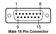
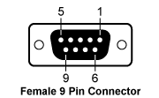
The pin descriptions shown in the first two tables below denote the typical pin assignments used by Thorlabs' family of laser diode temperature controllers and laser diode mounts. The third table gives the physical pin connections between the 15-pin and 9-pin sides of the CAB420-15 cable.
 |
|
| 1 | Status LED (+) (for TEC On/Off Indication)a |
| 2 | TEC Voltage Measurementb |
| 3 | Thermistor (-), Ground |
| 4 | Thermistor (+) |
| 5 | TEC (+) |
| 6 | TEC (+) |
| 7 | TEC (+) |
| 8 | LM 135/335 (-), Grounda |
| 9 | TEC Voltage Measurementb |
| 10 | Transducer AD 590/592 (-), LM 135/335 (+) |
| 11 | Transducer AD 590/592 (+), LM 135/335 (+) |
| 12 | No Connection |
| 13 | TEC (-), Status LED (-) |
| 14 | TEC (-), Status LED (-) |
| 15 | TEC (-), Status LED (-) |
 |
|
| 1 | Status LED (+) (for TEC On/Off Indication)a |
| 2 | Thermistor (+) |
| 3 | Thermistor (-), Ground |
| 4 | TEC (+) |
| 5 | TEC (-), Status LED (-) |
| 6 | No Connection |
| 7 | Transducer AD 590/592 (-), LM 135/335 (+) |
| 8 | LM 135/335 (-), Grounda |
| 9 | Transducer AD 590/592 (+), LM 135/335 (+) |
| Pin Connections | |
|---|---|
| 15-Pin Side | 9-Pin Side |
| 1 | 1 |
| 2 | 4 |
| 3 | 3 |
| 4 | 2 |
| 5 | 4 |
| 6 | 4 |
| 7 | No Connection |
| 8 | 8 |
| 9 | 5 |
| 10 | 7 |
| 11 | 9 |
| 12 | No Connection |
| 13 | 5 |
| 14 | 5 |
| 15 | No Connection |
 Products Home


 Zoom
Zoom T-Cube Temperature Controller