Optical Delay Lines
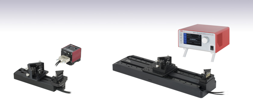
- Sub-Femtosecond Resolution with Up to 4000 ps Optical Delay
- Internal and External Triggering Modes
- High-Speed DC Servo Delay Stages Capable of Up to 400 mm/s
- Includes Low-Dispersion Silver-Coated Optics
ODL100
≤670 ps Optical Delay,
33 fs Delay Steps,
KBD101 Kinesis® Controller Included
ODL300
≤2000 ps Optical Delay,
0.67 fs Delay Steps,
BBD301 Benchtop Controller Included

Please Wait
Applications
- Pulsed Pump-Probe Experiments
- Autocorrelations, Cross Correlations, and Optical Sampling
- Pulse Synchronization
- Wavemeters and Other Interferometric Sensors
Features
- Optical Delays Up to 670 ps, 1470 ps, 2000 ps, or 4000 ps
- Minimum Delay Shift:
- 33 fs (ODL100)
- 0.67 fs (ODL220, ODL300, and ODL600)
- Computer Controlled via Kinesis® Software (Included)
- Triggering Modes for Forward and Reverse Scans:
- Internally Triggered Step Scan
- Externally Triggered Step Scan
- Externally Triggered Scan
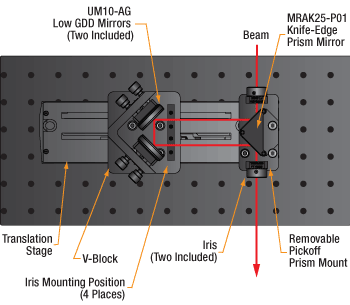
Thorlabs' Free-Space Optical Delay Lines (ODL) enable computer-controlled variation of the optical path length. Each system includes a DC servo stage, controller, and retroreflector optics with mounts. Each system also includes two drop-in irises with four mounting positions for alignment (see diagram to the right). Our UM10-AG Ultrafast-Enhanced Silver Mirrors and
If your application would benefit from other low GDD mirrors, please contact Technical Support to discuss the various options.
System Features
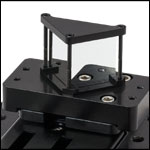
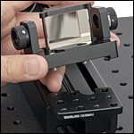
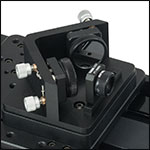
These compact systems are easily assembled and can be aligned using the included irises. As shown in the diagram to the right, the beam is steered at right angles by the right-angle prism mirror and the V-block, minimizing necessary alignment. Two SM05D5D irises mounted on twin steel dowel pins are provided; these pins are compatible with our FiberBench optic mounts and allow the irises to be quickly inserted and removed at four positions: two on the moving carriage and two adjacent to the right-angle prism, as shown in the photos below. The knife-edge prism mirror mount attaches to the end of the translation stage and can be repeatably removed and replaced if the user wishes to bypass the optical delay line, as shown in the photo below.
DC Servo Linear Translation Stages
Thorlabs' DC Servo Stages feature long travel ranges and can be driven at high speeds compared to stepper motor stages. This makes our ODL systems ideal for for high repetition rate experiments. High-speed scans can also be used to minimize the effects of slow changes in a system (such as thermal drifts) on experimental data.
Each stage uses direct drive technology that eliminates the need for a lead screw, enabling backlash-free operation. The absolute position of the stage is determined using a high-resolution, closed-loop optical feedback signal that provides superior bidirectional repeatability (please refer to the Specs tab for more information). Each stage also features a precision-grooved linear bearing that provides superior linearity and on-axis accuracy, making it well suited for a delay line setup.
Please note that when no power is applied, the stage platform can be moved manually, which may make these systems unsuitable for applications where the stage needs to remain in place when power is lost.
Accessories
For input and output beam alignment, we offer standard kinematic mounts and low drift Polaris® mounts (sold separately). Also, our periscope kit (sold separately) can be used to lower the beam height down to match our delay stages.
Click to Enlarge
Mount for Right-Angle Prism Mirror with Two Iris Locations
Click to Enlarge
Prism Mirror Mount is Easily Installed and Removed using Three 8-32 (M4) Cap Screws
Click to Enlarge
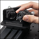
90° V-Block with Kinematic Retroreflector Mirror Mounts
Click to Enlarge
V-Block Also Includes Two Iris Locations
ODL100(/M)
| Specifications | |
|---|---|
| Item # | ODL100(/M) |
| Optical Delay Specifications | |
| Maximum Optical Delay | 670 ps |
| Inherent Delay @ 0 mm | 507 ps |
| Minimum Delay Shifta | 33 fs |
| Beam Height | 2.36" (60.0 mm) |
| Key Specifications of Translation Stageb | |
| Translation Stage Item # | DDS100(/M) |
| Travel Range | 100 mm (3.9") |
| Velocity (Max) | 500 mm/s |
| Acceleration (Max) | 5000 mm/s2 |
| Bidirectional Repeatability | ±1.5 µm |
| Minimum Incremental Movement | 5.0 µm |
| Absolute On-Axis Accuracy | ±6.5 µm |
| Pitch | ±175 µrad |
| Yaw | ±175 µrad |
| Bearing Type | High Rigidity, Recirculating, Precision Linear Bearings |
| Motor Type | Brushless DC Linear Motor |
| Dimensions | 195 mm x 57 mm x 35 mm (7.68" x 2.24" x 1.38") |
| Weight (with cables) | 0.72 kg (1.6 lbs) |
| List of Included Parts | ||
|---|---|---|
| Item # | Quantity | Description |
| DDS100(/M) | 1 | Linear Translation Stage |
| KBD101 | 1 | K-Cube™ Brushless DC Servo Controller |
| KPS201 | 1 | Power Supply for KBD101 Controller |
| UM10-AG | 2 | Ø1" Ultrafast-Enhanced Silver Mirror for 750 - 1000 nm |
| MRAK25-P01 | 1 | 1" Protected Silver Knife-Edge Right-Angle Prism Mirror |
| MH25 | 2 | Mirror Holder for Ø1" Optics |
| SM05D5D | 2 | Ring-Actuated Iris, Ø0.7 mm - Ø5.0 mm Beam Size |
| FT-SM05 | 2 | FiberBench Optic Mount |
| DDSMA1 | 1 | Left Mounting Plate for DDS100(/M) |
| N/A | 1 | Prism Mirror Mount |
| N/A | 1 | Pre-Aligned V-Block |
| Key Specifications of KBD101 Controllera | |
|---|---|
| Control Algorithm | 16-Bit Digital PID Servo Loop with Velocity and Acceleration Feedforward |
| Velocity Profile | Trapezoidal/S-Curve |
| Position Feedback | Incremental Encoder |
| Encoder Bandwidth | 2.5 MHz (10 M Counts/s) |
| Input Voltage | 14.5 - 15.5 V Regulated DC |
| Input Current | 2 A (Peak) |
| Dimensions | 60 mm x 60 mm x 49.2 mm (2.4" x 2.4" x 1.94") |
ODL220(/M), ODL300(/M), and ODL600(/M)
| Specifications | |||
|---|---|---|---|
| Item # | ODL220(/M) | ODL300(/M) | ODL600(/M) |
| Optical Delay Specifications | |||
| Maximum Optical Delay | 1470 ps | 2000 ps | 4000 ps |
| Inherent Delay @ 0 mm | 507 ps | 607 ps | 607 ps |
| Minimum Delay Shifta | 0.67 fs | 0.67 fs | 0.67 fs |
| Beam Height | 3.22" (81.7 mm) | 3.45" (87.7 mm) | 3.45" (87.7 mm) |
| Key Specifications of Translation Stageb | |||
| Translation Stage Item # | DDS220(/M)c | DDS300(/M)d | DDS600(/M)e |
| Travel Range | 220 mm (8.6") | 300 mm (11.81") | 600 mm (23.6") |
| Velocity (Max) | 300 mm/s | 400 mm/s | 400 mm/s |
| Acceleration (Max) | 5 000 mm/s2 | 10 000 mm/s2 | 10 000 mm/s2 |
| Bidirectional Repeatability |
±0.25 µm | ±0.25 µm | ±0.25 µm |
| Minimum Incremental Movement |
0.1 µm | 0.1 µm | 0.1 µm |
| Absolute On-Axis Accuracy |
±2.0 µm | ±7.5 µm | ±12.0 µm |
| Pitchf | ±175 µrad | ±100 µrad | ±150 µrad |
| Yawf | ±175 µrad | ±150 µrad | ±300 µrad |
| Bearing Type | Precision Linear Bearing | High Rigidity, Recirculating, Precision Linear Bearings | |
| Motor Type | Brushless DC Linear Motor | ||
| Dimensions | 370.0 mm x 90.0 mm x 44.0 mm (14.57" x 3.54" x 1.73") |
500 mm x 130 mm x 50 mm (19.69" x 5.12" x 1.97") |
800 mm x 130 mm x 50 mm (31.5" x 5.12" x 1.97") |
| Weight | 2.4 kg (5.3 lbs) | 5.9 kg (12.98 lbs) | 9.125 kg (20.0 lbs) |
| List of Included Parts | ||
|---|---|---|
| Item # | Quantity | Description |
| (See Footnote a) |
1 | Linear Translation Stage |
| BBD301 | 1 | 1-Channel Brushless DC Servo Controller |
| UM10-AG | 2 | Ø1" Ultrafast-Enhanced Silver Mirror for 750 - 1000 nm |
| MRAK25-P01 | 1 | 1" Protected Silver Knife-Edge Right-Angle Prism Mirror |
| MH25 | 2 | Mirror Holder for Ø1" Optics |
| SM05D5D | 2 | Ring-Actuated Iris, Ø0.7 mm - Ø5.0 mm Beam Size |
| FT-SM05 | 2 | FiberBench Optic Mount |
| N/A | 1 | Mounting Plates for Translation Stage |
| N/A | 1 | Prism Mirror Mount |
| N/A | 1 | Pre-Aligned V-Block |
| Key Specifications of BBD301 Controller | |
|---|---|
| Control Algorithm | 16-Bit Digital PID Servo Loop with Velocity and Acceleration Feedforward |
| Velocity Profile | Trapezoidal/S-Curve |
| Position Feedback | Incremental Encoder |
| Encoder Bandwidth | 2.5 MHz (10 M Counts/s) |
| Input Power Requirements | Power: 250 VA Voltage: 100 to 240 V AC Frequency: 47 to 63 Hz Fuse: 3.15 A |
| Dimensions | 199.8 mm x 229.1 mm x 108.8 mm (7.87" x 9.02" x 4.28") |
Each optical delay line kit includes four UM10-AG Ultrafast-Enhanced Silver Mirrors and one MRAK25-P01 Protected Silver Knife-Edge Right-Angle Prism Mirror. If your application would benefit from other low GDD mirrors, please contact Technical Support to discuss the various options.
Low GDD Mirrors (UM10-AG)
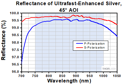
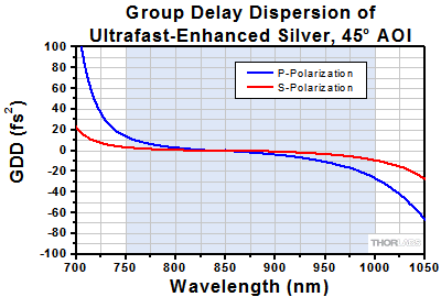
The UM10-AG is specifically designed for use with femtosecond Ti:Sapphire lasers. In the 750 - 1000 nm wavelength range, it provides RS > 99.0%, RP > 98.5%, |GDD| <20 fs2 for S-polarized light, and |GDD| <30 fs2 for P-polarized light.
The graphs below represent the measured reflectance and theoretically calculated group delay dispersion (GDD) of the ultrafast-enhanced silver coating. The shaded regions denote the wavelength range over which we guarantee the mirrors will meet the specifications stated above. Performance outside the shaded regions will vary from lot to lot and is not guaranteed.
Protected Silver Knife-Edge Right-Angle Prism Mirror (MRAK25-P01)
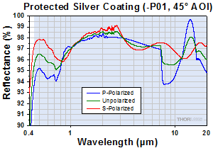
The protected silver coating on the MRAK25-P01 provides >96% average reflectance from 450 nm to 20 µm. While a bare silver coating has almost no dispersion, some silver mirrors do feature a dielectric coating, which can increase the dispersion, especially when the dielectric coating is used to enhance spectral features. Our protected silver mirrors feature a dielectric coating for protection of the fragile silver coating, and this coating has only a negligible effect on the dispersion.
The shaded region in the graph denotes the range over which we recommend using this mirror. Please note that the reflectance outside of this band is not as rigorously monitored in quality control, and can vary from lot to lot, especially in out-of-band regions where the reflectance is fluctuating or sloped.
Software
Kinesis Version 1.14.50
The Kinesis Software Package, which includes a GUI for control of Thorlabs' Kinesis system controllers.
Also Available:
- Communications Protocol

Kinesis GUI Screen
Thorlabs offers the Kinesis® software package to drive our wide range of motion controllers. The software can be used to control devices in the Kinesis family, which covers a wide variety of motion controllers ranging from small, low-powered, single-channel drivers (such as the K-Cubes™) to high-power, multi-channel benchtop units and modular 19" rack nanopositioning systems (the MMR60x Rack System).
The Kinesis Software features .NET controls which can be used by 3rd party developers working in the latest C#, Visual Basic, LabVIEW™, or any .NET compatible languages to create custom applications. Low-level DLL libraries are included for applications not expected to use the .NET framework and APIs are included with each install. A Central Sequence Manager supports integration and synchronization of all Thorlabs motion control hardware.
By providing this common software platform, Thorlabs has ensured that users can mix and match any of our motion control devices in a single application, while only having to learn a single set of software tools. In this way, it is perfectly feasible to combine any of the controllers from single-axis to multi-axis systems and control all from a single, PC-based unified software interface.
The software package allows two methods of usage: graphical user interface (GUI) utilities for direct interaction with and control of the controllers 'out of the box', and a set of programming interfaces that allow custom-integrated positioning and alignment solutions to be easily programmed in the development language of choice.
Legacy Software
Select products are still capable of running the legacy APT™ software package. Information on software compatibility can be found in the product documentation (![]() ), and additional details about the APT software can be found here.
), and additional details about the APT software can be found here.
| Posted Comments: | |
user
(posted 2024-04-01 15:27:16.07) I have lost a knife edge prism and a removal pickoff prism mount block, as well as the adapter that connects the prism mount to DDS220/M. Could you please inform me if it's possible to purchase these items separately?
Can you please provide a quote if it's possible to purchase these items separately? jpolaris
(posted 2024-04-08 12:57:06.0) Thank you for contacting Thorlabs. Requests for component parts such as the knife edge prism and mount block that come with ODL220/M can be made by emailing us at techsupport@thorlabs.com. I have reached out to you directly to arrange getting these parts to you. Daniela Serien
(posted 2023-06-09 17:16:29.853) I just assembled ODL100/M. I would like to give feedback and maybe receive some assistence in substitution of the damage parts if Thorlabs does that.
The manual said "the top plate of the holder is gently tightened against the prism by three locking screws with a 5/64” hex head." but in this step the prism was damaged and here is why:
Here are the problems points exactly:
1. the black screws to hold the prism cap, 2 of 3 were not perfectly straight, I was aware that they would not need to go in completely, so I assumed they passed Thorlabs test.
2. all of them did not neatly fit into their holes (by hand I could enter 3-5 turns, then it was very hard to move)
3. there were some allen wrenches, but for 2 types of screws, one of which the thin black prism holding one, were NOT provided with an allen wrench.
4. I was confused, maybe I misunderstood how the cap should be lowered and used the manual page 3 (which has not a close-up) and this image:
https://www.thorlabs.com/images/TabImages/Prism_Mirror_Mount_A2-780.jpg which does not look like the items I worked with, but gave me the impression to screw in the screws fully. After that, I attempted to gently screw by alternating the screws to lower it evenly, but because the screws were so hard to handle and went in uneven, pressure was generated in one point and cracked the prism on the side.
5. The wepage and the manual suggest, the prism (gently) to be clamped, but after handling it, I dont think that was feasible.
In conclusion,
1) if there is any Thorlabs service that would provide a substitue or a reduced price on the repurchase, I would be pleased to hear it. (also, do I need to repurchase the screws or the prism holder as a whole as well? they were really hard to handle)
I think further that
1) a close-up picture of this particular step should be in the manual, what is the "gently pressed" position, how far are the screws in, what is acceptable in screw quality etc..
2) a list of the items used and their product code for re-purchase should be included
3) allen wrench for the rare screws that are critical to holding the prism should be provided
4) the manual says the cap is "gently pressed", but is that even the function of the cap? it seems the cap design will fail to actually hold the prism (e.g. if I wanted to use the delay line in a vertical beam line). Would it not be better to not provide the cap if it is not meant to clamp. I mean, after attempting assembly, the cap seems cosmetic. It suggests a function, but has none. the manual should not encourage to press (whatsoever, I was gentle, tried my hardest to manage the screws without being uneven on the prism).
Thank you very much for reading this. Whether or not there can be any help towards my already broken prism is without expectation. I just really think the prism cap is a trouble spot (quality of the screws, instructions, cap design) and wanted to give feedback. jpolaris
(posted 2023-06-15 01:13:31.0) Thank you for contacting Thorlabs. I am sorry to hear that you have experienced issues in the setup process for your ODL100/M. The threads needed to secure the top clamp to the prism are minimal, only requiring at most 3 to 5 turns. I have reached out to you to discuss this further, as well as to assist in arranging replacements for any damaged components. We will look into how we can improve the clarity of the manual in order to prevent this issue from arising in the future. Yujiao Jiang
(posted 2023-05-15 16:19:22.103) We would like to order the Pre-Aligned V-Block with 90degree, but in the List of Included Parts it says N/A, I can't find it by key words or in catalogue as well, can you please help me find it?
https://www.thorlabs.com/newgrouppage9.cfm?objectgroup_id=5521 jpolaris
(posted 2023-05-19 01:58:20.0) Hello, thank you for contacting Thorlabs. Component items such as the Pre-Aligned V-Block for these Optical Delay Lines can be requested by contacting us at techsupport@thorlabs.com. I have reached out to you directly to arrange this. Svitlana Pavlova
(posted 2022-06-28 16:58:14.29) Hello. What is the resolution for models ODL220 and ODL100?
Thank you. cdolbashian
(posted 2022-07-06 11:10:11.0) Thank you for reaching out to us Svitlana. These data can be found in the "Specs" Tab on the product page under the value "Minimum Delay Shift". user
(posted 2021-11-27 23:22:59.557) Dear Madam or Sir, can one BBD301 control two delay lines simultaneously? If it can, can I buy a ODL220 as well as a ODL600 but with only one BBD301 to make the price lower? Thanks in advance! YLohia
(posted 2021-11-30 02:42:26.0) Hello, thank you for contacting Thorlabs. The BBD301 is a single channel controller and, thus, incapable of controlling multiple stages at the same time. Assuming you meant the BBD302 2-channel controller, yes, that can be used to control two stages simultaneously. If you would like to modify the existing kit, please email your local Thorlabs Tech Support team (in your case, techsupport-cn@thorlabs.com). Sergej Safonov
(posted 2021-10-18 10:49:49.36) How to change the home position of the delay line? azandani
(posted 2021-10-26 09:32:43.0) Hello Sergej, thank you for contacting Thorlabs. Unfortunately, there is no way to change the home position of the delay line. This is set during manufacturing. ABHISHEK GUPTA
(posted 2020-09-16 07:59:40.69) Is it compatible with XPS motion controller from Newport? YLohia
(posted 2020-09-16 10:48:14.0) Thank you for contacting Thorlabs. These units are only compatible with the controllers listed on this page. user
(posted 2019-05-20 09:53:38.703) 驱动软件存在问题:当使用pSec单位调节延迟线时,输入特定的数值(pSec),点击"move"之后,延迟线就自动回到“零”位置,所以只能通过精度更差的mm单位调节延迟线。 asundararaj
(posted 2019-05-21 12:14:12.0) Thank you for contacting Thorlabs. Our Technical Support Team in China will reach out to you directly to troubleshoot your issues with the ODL move command. simon.neves
(posted 2018-10-11 11:39:13.607) Hello,
Would this be possible to purchase this product with dieletric mirrors and knife-edge, coated for 1550nm, instead of the silver-coated mirrors ? nbayconich
(posted 2018-10-11 04:53:11.0) Thank you for contacting Thorlabs. I'll reach out to you directly to discuss your application and our custom capabilities. jys2316
(posted 2018-09-16 22:33:12.337) Are there any labview vi files to control this stage? I cannot find it. Thanks nbayconich
(posted 2018-09-19 03:00:45.0) Thank you for contacting Thorlabs. The current ODL software does not interface with labview, however you can use our APT or Kinesis motion control software to communicate with the BBD201 controller included in the kit. Please see our APT and Kinesis motion control software tutorials located in the links below for step by step guides on how to interface with labview.
APT
https://www.thorlabs.com/newgrouppage9.cfm?objectgroup_id=8348
Kinesis
https://www.thorlabs.com/newgrouppage9.cfm?objectgroup_id=10285
Several sample labview .vi's can be downloaded directly from the links above. tpengineeringservices
(posted 2018-06-06 13:38:18.66) I would like to purchase the V block only for a 1" mirror mount (I have mirrors). I emailed techsupport, but haven't heard back from anyone.
Thanks llamb
(posted 2018-06-08 05:05:35.0) Hello, thank you for contacting Thorlabs and I apologize for the delay in response. We try and contact customers for new email requests within 24 hours. I see that you were already contacted on June 7th by a member of Tech Support regarding this request, as we can indeed offer the V-block assembly as a custom product. Any further customization or quotes will be handled by email. lebouquj
(posted 2017-10-17 17:27:07.897) I am not sure to understand why the pitch and yaw have similar value. The 90deg V-Block shall cancel most of the yaw, isn't it? Am I wrong? Thanks. tfrisch
(posted 2017-10-17 03:50:41.0) Hello, thank you for contacting Thorlabs. The pitch and yaw specs listed are for the DDSM100 stage, not the beam itself. I will reach out to you directly to discuss this. james.david.good
(posted 2017-05-23 15:35:51.627) Hi,
are there any figures of merit on the pitch and yaw variance of the stages? I've found the compact motorized stages to be unsuitable for measurements owing to this fact. bwood
(posted 2017-07-18 05:09:59.0) Response from Ben at Thorlabs: Thank you for your feedback. The pitch and yaw of the stages used in these kits can be found on the "Specs" tab of this webpage. All of our specifications are based on experimental data, and if you would like to discuss this data further, please feel free to contact me at techsupport.uk@thorlabs.com chiwon.lee
(posted 2016-10-05 08:34:08.86) Hello,
I'm using the 220 mm delay line stage, and want to purchase the "V-block" system, separately. Could you please contact me? jlow
(posted 2016-10-05 02:15:51.0) Response from Jeremy at Thorlabs: Yes we can provide this separately. I will contact you about the quote. You can also request a quote by emailing us at techsupport@thorlabs.com. user
(posted 2016-09-23 14:09:38.907) Optical height is 2.4"/60mm. However 2.4 inch is converted to 61mm. On the other hand minimum aperturesize is 0.07mm. 60mm or 61mm is big difference against the 0.07mm. What would be correct information? jlow
(posted 2016-09-27 02:04:30.0) Response from Jeremy at Thorlabs: Thank you for pointing out the optical height issue. The measurement from the center of the iris on the stage (beam center), perpendicular to the breadboard or table, is 2.554” (64.87mm). We will be updating this on the web and manual. philipp.kucirek
(posted 2016-01-26 13:59:38.647) Hi,
is it possible to purchase the "Mount for Right-Angle Prism Mirror with Irises" and the "V-Block" of the ODL100-FS/M separately?
Thanks and regards besembeson
(posted 2016-02-01 10:53:21.0) Response from Bweh at Thorlabs USA: Yes this is possible. |

| Key Specsa | |
|---|---|
| Item # | ODL100(/M) |
| Optical Delay (Max) | 670 ps |
| Minimum Delay Shift | 33 fs |
| Translation Stage Item # | DDS100(/M) |
| Stage Velocity | 500 mm/s |
| Absolute On-Axis Accuracy |
±6.5 µm |
- System Includes:
- 100 mm Travel DC Servo Linear Translation Stage
- KBD101 Compact Kinesis® Controller
- Mirrors and Knife-Edge Prism
- Stage Adapters and Optic Mounts
- Refer to Specs Tab for Complete Kit Contents
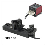
The ODL100(/M) Optical Delay Line offers up to 670 ps of optical delay and includes a 100 mm translation stage, a compact DC servo stage controller, optics, and mounting hardware. A knife-edge prism at one end of the translation stage reflects the beam towards two V-block-mounted mirrors on the translating platform.

Click to Enlarge
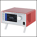
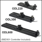
BBD301 Controller Included
| Key Specsa | |||
|---|---|---|---|
| Item # | ODL220(/M) | ODL300(/M) | ODL600(/M) |
| Optical Delay (Max) | 1470 ps | 2000 ps | 4000 ps |
| Minimum Delay Shift | 0.67 fs | ||
| Translation Stage Item # | DDS220(/M) | DDS300(/M) | DDS600(/M) |
| Stage Velocity | 300 mm/s | 400 mm/s | 400 mm/s |
| Absolute On-Axis Accuracy |
±2.0 µm | ±7.5 µm | ±12.0 µm |
- Systems Include:
- DC Servo Linear Translation Stage
- BBD301 Benchtop Controller
- Mirrors and Knife-Edge Prism
- Stage Adapters and Optic Mounts
- Refer to Specs Tab for Complete Kit Contents
These optical delay lines include a translation stage, benchtop DC servo stage controller, optics, and mounting hardware. A knife-edge prism at one end of the translation stage reflects the beam towards two V-block-mounted mirrors on the translating platform.
 Products Home


 Zoom
Zoom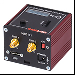
 Optical Delay Lines