Tip, Tilt, and Rotation Stage
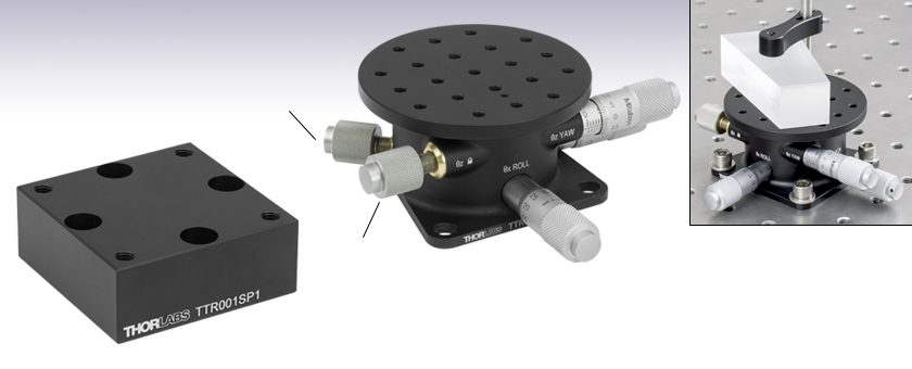
- ±5° Tip and Tilt
- ±10° Rotation
- Micrometer Positioning
Adjusts Pitch and
Roll Preload
Adjusts Yaw
Preload
TTR001SP1
62.5 mm (2.46") Deck Height Adapter
TTR001
Provides Tip, Tilt, and Rotation
TTR001 Stage with a PM3
Clamping Arm, Holding a Prism

Please Wait
| Item # | TTR001(/M) | |
|---|---|---|
| Tip/Tilt (Pitch and Roll) Adjustment Range | ±5° | |
| Tip/Tilt (Pitch and Roll) Micrometer Resolution | 0.036° | |
| Rotation (Yaw) Adjustment Range | ±10° | |
| Rotation (Yaw) Micrometer Resolution | 0.03° | |
| Deck Height | 1.48" (37.5 mm) | |
| Deck Height with TTR001SP1(/M) Mounting Plate | 2.46" (62.5 mm) | |
| Load Capacitya,b (Max) | 11.0 lbs (5.0 kg) | |
| Construction | Aluminum | |
| Finish | Black Anodized | |
Features
- Micrometer Operated Tip, Tilt, and Rotation
- 8-32 (M4) Tapped Holes with 1/2" (12.5 mm) Spacing
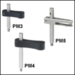
- Can be Used with PM3(/M), PM4(/M), and PM5(/M) Clamping Arms
- Imperial Versions Include 8-32 to 6-32 Adapter for Compatibility
- Metric Versions are Directly Compatible
- 1.48" (37.5 mm) Deck Height
- Black Anodized Aluminum Construction
The TTR001(/M) Tip, Tilt, and Rotation Stage provides ±5° uncoupled tilt adjustment in pitch and roll, together with ±10° rotation (yaw) adjustment. These adjustments allow optical components and fixtures to be aligned with a plane and then rotated within that plane. The center of rotation axis is located at a line normal to the center of the platform. Both the tip and tilt axes will move with respect to a point located 12 mm below the top surface of the stage on the rotation axis. The top plate features an array of 21 8-32 (M4) threaded holes on a 1/2" (12.5 mm) pitch. An 8-32 to 6-32 thread adapter is included with imperial stages for use with the PM3 and PM4 clamping arms sold below. The PM5 is directly compatible with the imperial stages, and all metric clamping arms are directly compatible with the metric stages; these combinations do not require an adapter.
Click to Enlarge
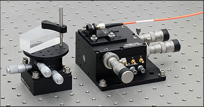
TTR001 stage raised to same deck height as MAX311D stage for use in a typical refraction application. The prism is held in place by a PM3 clamping arm attached to the stage using a thread adapter, which is included with the TTR001.
The high-resolution Mitutoyo micrometers incorporated into the stage are marked with a 0.001" (10 µm) scale. Turning the micrometers gives 1.5° of rotation (with a resolution of 0.03°) and 1.78° of tilt per revolution (with a resolution of 0.036°). Preload adjustment to eliminate backlash can be performed by adjusting the knobs adjacent to the micrometers as shown above. One knob adjusts/locks the pitch (Θx) and roll (Θy) axes simultaneously, while the other knob adjusts/locks the yaw (Θz) axis. Note that if the knob is tightened, the motion in that axis is effectively locked until the micrometer is backed off. In this case, some friction may be experienced when adjusting the remaining axis.
The stage is fixed to the work surface via three clearance holes for standard 1/4"-20 (M6) screws. The deck height of the stage is 1.48" (37.5 mm). A Height Adapter Plate [TTR001SP1(/M)] is available to raise the deck height to the standard 2.46" (62.5 mm), making the stage compatible with our NanoMax, MicroBlock, and RollerBlock 3-Axis Stages. The height adapters are fixed to the work surface using the four clearance holes that accept standard 1/4"-20 (M6) screws. The stage is then mounted to the height adapter using the three 1/4"-20 (M6) tapped holes.
A typical application is shown to the right, where the TTR stage is raised up to mate with a MAX311D 3-axis stage. A PM4 clamping arm is used to mount a Pellin Broca prism on the tip, tilt, and rotation stage. An HCS209 Mount and previous-generation HFB004 fiber holder are mounted on the MAX311D stage and used to hold a collimating lens with connectorized fiber. The collimated laser beam is directed onto the prism, and the laser refraction is adjusted via the TTR001 stage micrometers.
| Posted Comments: | |
user
(posted 2024-08-06 08:48:02.7) Is this stage compatible with the DRV modular piezoelectric actuator as a substitute/addition to the micrometers? dnewnham
(posted 2024-08-12 04:23:05.0) Thank you for your feedback. This stage is not able to be driven by a different actuator. This is due to the micrometers being bonded in place as such they cannot be removed without possibly damaging the stage. I will reach out to you directly to discuss your application. Andi ...
(posted 2023-04-21 06:06:05.03) Can the stage handle off center load? If yes, is there a formula to calculate the max. allowed off center load?
Thanks in advance JReeder
(posted 2023-04-24 03:29:49.0) Thank you for your enquiry. We do not have any data for the maximum off-axis load that this stage can hold. We will reach out to you to discuss your particular application. Joel Humes
(posted 2023-04-04 12:54:12.047) I am looking to attach this TTR001 (Tip, Tilt, Rotation) stage on top of a couple of LNR502E (rotary encoded stepper stages) which will actuate in X and Y directions, and all of this on top of a high load MLJ150/M (Z stage) but I am concerned with how much weight this stack will come out to.
How much does this TTR001 (Tip, Tilt, Rotation) stage weigh?
Thank you JReeder
(posted 2023-04-05 08:36:00.0) Thank you for your enquiry. The total mass of the TTR001 is 0.3 kg. I have reached out to you directly to see if you require any further information. Arthur Kenton
(posted 2022-12-12 16:50:18.333) We're trying to determine if a total of 15# load can be cantilevered about 6 inches offset from the vertical axis of the TTR1 (which has a spec of 11lbs). I have a pdf diagram I can send. do'neill
(posted 2022-12-16 06:52:34.0) Response from Daniel at Thorlabs: Thank you for your inquiry. We do not have a spec for any off-axis or cantilevered load but as your load is above even the on-axis load this will not work for your application. We will reach out to you to discuss your particular application. Aaron Schweihofer
(posted 2020-04-01 15:15:23.363) I am using Solidworks2015 and am not able to download the model, do you have an older version so I can use this part in a design? DJayasuriya
(posted 2020-04-02 05:56:46.0) Response from Dinuka at Thorlabs: Thanks for your query. I will get in touch directly to help with this issue. Thank you. WONSANG LEE
(posted 2019-12-06 00:56:16.63) Dear sir,
We have this product, TTR001/M, in our company, but θy pitch does not work now. We do not have any idea about this problem.
The micrometer head seems like stuck even though we turn it by force.
How we can solve this problem? Please give us your advice.
Thank you. cwright
(posted 2019-12-09 11:25:14.0) Response from Charles at Thorlabs: Hello Wongsang, I'm sorry to hear that you are having this issue. There are a few potential causes which require some troubleshooting so I will ask your local technical support team reach out to you directly to resolve this. emmanuel.cherin
(posted 2018-11-28 12:28:58.123) Hi,
Could the TTR001 stage could be used in a suspended, upside down position, and if it is possible what would be the maximum load (centered) ?
Thank you AManickavasagam
(posted 2018-11-29 06:55:17.0) Response from Arunthathi @ Thorlabs: Thanks for your query. The stage is only tested for the upright orientation and we would not be able to guarantee that you could achieve the specifications stated on the website when used upside down.
If you could contact techsupport directly with details of your set up (mass and momentum) we could may be replicate and test this for you. devin.metante
(posted 2016-12-10 16:15:47.343) Please provide/contact me for spec if mounted vertically. Thanks tfrisch
(posted 2016-12-19 02:07:10.0) Hello, thank you for contacting Thorlabs. TTR001/M is not intended to be mounted on a vertical surface. I will reach out to you directly with more details. Performance will likely come down to what load needs to be mounted. david.blum
(posted 2015-04-29 17:02:34.587) Hello! Is it possible to upgrade the micrometer screws on this rotation stage? How can the stock screws be dismounted? What micrometer screws would fit this stage? Thank you very much! rcapehorn
(posted 2015-04-30 10:15:31.0) Response from Rob at Thorlabs: At this moment in time we are not offering any other options of drive for this stage. Unfortunately the current drives are bonded in place, therefore they cannot be removed easily without damaging the stage. Therefore it will not be possible for you to modify this stage. rmal
(posted 2014-10-30 12:01:20.56) I was wondering why not adding, on the top of the TTR001/M, a "coarse" rotation stage. This way one could decide a rough "incidence angle" first and then adjust it using the micrometer screws. Very useful for applications where various angles are needed, but all with high degree of precision. msoulby
(posted 2014-11-03 04:01:58.0) Response from Mike at Thorlabs: Thank you for your feedback regarding this stage. I have forwarded your enquiry to the engineering team to see what would be involved in adding a rotating top plate to this stage. We will contact you directly with more details about what might be possible. xi.wang
(posted 2014-09-03 01:41:29.897) Hi Ben, we need something like this but mounted vertically with the main axis horizontal. The load (a vertical stylus or rod) will be 2 kg. When running the experiment, a horizontal force (<5N) will be applied to the stylus. Is this product able to handle this? Thank you very much. Xi bhallewell
(posted 2014-09-04 07:08:19.0) Response from Ben at Thorlabs: Thank you for your question here. As a result of previous feedback we are currently undergoing tests to spec the performance of this stage when vertically mounted. I will contact you directly to advise on your application in detail. miroslav.andrle
(posted 2014-06-19 05:02:19.583) Hello,
we're probably going to use this stage in our project but we have some trouble with enough space there so we need to try a few ways of concept to find the right fit. What i'd like to know is, if it's okay for this stage to work upside down or with the main axis in horizontal orientation.
Thank you
Best regards
M. Andrle bhallewell
(posted 2014-06-20 12:18:51.0) Response from Ben at Thorlabs: We currently do not hold load specifications for this stage when mounted vertically as the stage is designed specifically for table mounted use. I will contact you directly to discuss your requirements further. extern.marcel.liebhart
(posted 2014-06-16 16:33:59.767) Hello,
I need some informations about the Load limits for all axis (X, Y, Z, Θx, Θy, and Θz) force and moment
Thanks and Best Regards bhallewell
(posted 2014-06-18 12:25:21.0) Response from Ben at Thorlabs: We appreicate your feedback here. We spec the load capacity at 5kg on the webpage. This would account for the load limit for adjustment in dx, dy & dz (tip, tilt & rotation) only. We will contact you for further details of your requirements. rnewstrom
(posted 2013-07-08 13:39:39.16) What is the typical center of rotation for each axis on your TTR001 tip, tilt and rotation stage? cdaly
(posted 2013-07-09 10:23:00.0) Response from Chris at Thorlabs: Thank you for using our feedback tool. The rotation axis will cause movement about the line normal to the center of the platform. The tip and tilt axis will move about a point 12 mm below the top surface of the platform located on the rotation axis. |

Click for Details
Mechanical Drawings
- Provide Clamping Force for Our Platform Mounts
- Threaded Hole on Top and Threaded Stud on Bottom of Post
- 6-32 Threads on PM3 and PM4
- 8-32 Threads on PM5
- M4 x 0.7 Threads on All Metric Versions
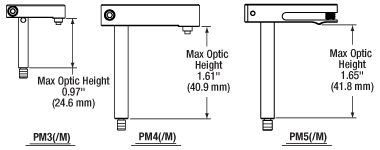
- Maximum Optic Heights from 0.97" to 1.65" (24.6 mm to 41.8 mm)
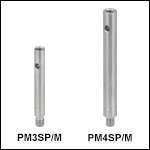
- Extension Posts Available to Increase Max Optic Height
- PM3SP(/M) with PM3(/M): Hold Optics up to 2.21" (56.1 mm) Tall
- PM4SP(/M) with PM4(/M): Hold Optics up to 3.61" (91.7 mm) Tall
Click to Enlarge
Clamping Arm Extension Posts with Metric Indicator Groove
Thorlabs' Clamping Arms provide clamping force to secure optics to our kinematic platform mounts, stages, and V-clamps. The PM3(/M) accommodates optics up to 0.97" tall and features a 0.69" center-to-center distance between the post and the nylon-tipped setscrew that holds the optic. The PM4(/M) accommodates optics up to 1.61" and features a 1.16" center-to-center distance between the post and the nylon-tipped setscrew. The maximum optic height of the PM3(/M) or PM4(/M) Clamping Arms can be extended using our PM3SP(/M) or PM4SP(/M) Extension Posts, respectively. These extension posts are identical to the posts included in each complete clamping arm. Each clamping arm features 6-32 (M4 x 0.7) threads. The PM3 and PM4 can be mounted in 8-32 tapped holes by using the AS6E8E thread adapter, which features internal 6-32 threads and external 8-32 threads. This thread adapter has an outer diameter of 0.24", which is the same as the PM4SP extension post and the post included with the PM4 clamping arm. This allows the clamping arm to be adjusted across the seam between either post and the adapter. The smaller diameters of the included post for the PM3 clamping arm and the PM3SP extension post cause the thread adapter to act as a stop for the clamping arm.
The PM5(/M) clamping arm is made entirely from heat-treated stainless steel, which helps maintain stability in fluctuating temperatures and provides vacuum compatibility. This clamping arm is recommended for use with the POLARIS-K1M4(/M), but it can be used with any platform mount or stage that has one or more 8-32 (M4 x 0.7) tapped holes. The PM5(/M) can hold optics up to 1.65" tall, and the distance from the post center to the contact point that holds the optic is 0.90".
Each clamping arm is attached to its post using a flexure mechanism that locks with a 5/64" (2.0 mm) balldriver or hex key. The setscrew on top of the clamping arm also accepts a 5/64" (2.0 mm) balldriver or hex key in order to clamp down on the optic. The post includes a through hole which can be leveraged for added torque when tightening down the post. Please see the diagram above for additional information.
 Products Home


 Zoom
Zoom Tip, Tilt, and Rotation Stage