Kinesis® K-Cube™ Piezo Inertia Actuator Controller
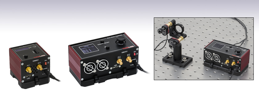
- Open-Loop Piezo Inertia Actuator Controllers
- Operation via Top Panel Controls or Remote PC via USB
- Single- or Multi-Channel Controllers Available
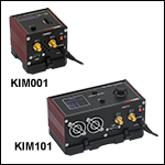
KIM101
Four-Channel K-Cube Piezo Inertia Motor Controller
Application Idea
The KIM101 Controller features four channels, making it ideal for use with mirror mounts and beam steering applications.
KIM001
Single-Channel K-Cube Piezo Inertia Motor Controller

Please Wait
Click to Enlarge
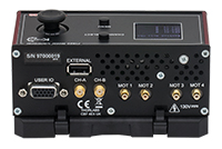
Back View of the KIM101 Controller (See the Pin Diagrams Tab for More Information)
Click to Enlarge
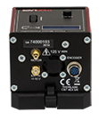
Back View of the KIM001 Controller (See the Pin Diagrams Tab for More Information)
| K-Cube™ Motion Control Modules |
|---|
| Brushed DC Servo Motor Controller |
| Brushless DC Servo Motor Controller |
| Fiber Alignment Controllers |
| Four-Channel Piezo Inertia Actuator Controller |
| PSD Auto Aligner |
| Single-Channel Piezo Controller and Strain Gauge Reader |
| Solenoid Controller |
| Stepper Motor Controller |
Features
- Compact Footprints
- Adjustable Voltage Output from 85 V to 125 V
- Single-Channel and Four-Channel Versions Available
- ±10 V Analog Input (SMA Female, See Pin Diagrams Tab for Details)
- Includes Kinesis® and APT™ Software Control Suites
Thorlabs' K-Cube™ Piezo Inertia Motor Controllers are part of Thorlabs' Kinesis® line of high-end, compact motion controllers. They are designed to drive our standard and vacuum-compatible piezo inertia actuators, PD1 Series
20 mm Translation Stages, PDR1(/M) Rotation Stage, and PIM Series Piezo Inertia Optic Mounts. They are also compatible with our PD2(/M) 5 mm Translation Stage and PD3(/M) 50 mm Translation Stage when used with the PD2AD Adapter Cable. The KIM001 single-channel controller provides a voltage output for a single piezo inertia device, while the KIM101 four-channel controller offers up to four outputs with single- or dual-channel operation, making it ideal for applications such as beam steering and positioning.
Each unit has a compact footprint, allowing it to be positioned close to the motorized system for added convenience when adjusting motor positions using the top panel controls. The included mounting plate can be secured to an optical table via two 1/4" (M6) counterbored slots. Alternatively, two magnets in the mounting plate can secure the assembly to the optical table for quick, drop-in operation.
A power switch on the front of the unit turns the controller on and off. The top panel display screen enables operation as soon as the unit is turned on, without the need for connection to a PC. When the switch is turned off, the K-Cube saves all user-adjustable settings for the next session. Please note that the power switch should always be in the "off" position when plugging in or unplugging the unit.
USB connectivity provides easy 'Plug-and-Play' PC-controlled operation with our Kinesis software package. The Kinesis Software features new .NET controls which can be used by 3rd party developers working in the latest C, C#, LabVIEW™ or any .NET compatible languages to create custom applications. These controllers are also compatible with our legacy APT™ software, which is based in the ActiveX® programming environment. Both the Kinesis and APT software packages provide advanced movement control that allow the user to quickly set up complex move sequences. For example, all relevant operating parameters are set automatically by the software for Thorlabs piezo inertia devices. For more details on both software packages, please see the Motion Control Software, Kinesis Tutorials, and APT Tutorials tabs.
Each K-Cube features two bidirectional trigger ports that can be used to read an external logic signal or output a logic level to control external equipment. When a port is used in the input mode, the logic levels are TTL compatible. When used in the output mode, the port provides a push-pull drive of 5 V, with the maximum current limited to approximately 8 mA. Please see the manual for more information.
Note: When used with the PD1(/M) linear translation stage or PDR1(/M) rotation stage, the KIM101 controller version must be 2019 or newer (per the S/N label) and be running a compatible revision of the firmware. The PD1(/M) translation stage requires firmware revision of 010003 or higher (indicated when the controller is powered on), while the PDR1(/M) rotation stage requires firmware revision 010004 or higher. Earlier versions of the KIM101 controller or those with older firmware will not function properly with a PD1(/M) or PDR1(/M) stage and may cause failure of the stage and/or the controller.
Power Supply
The KIM001 and KIM101 Motor Controllers do not ship with a power supply. A compatible power supply (Item # KPS201), is available separately below.
Note: Due to the nature of its design, and its non-linear high frequency switching, the KIM001 and KIM101 units are not compatible with the KCH301 and KCH601 hubs. Only use the KPS201 power supply unit.
| Item # | KIM001 | KIM101 |
|---|---|---|
| Piezoelectric Outputs | One SMC Male | Four SMC Male |
| Voltage Output | 85 to 125 VDC | 85 to 125 VDC per Channel |
| External Input | SMA | SMA, CH-A, CH-B |
| Input Type | Single Ended, Analog | |
| Input Voltage | ±10 V ± 2%a | |
| Output Configuration | - | Individual Channels: Ch 1, Ch 2, Ch 3, Ch 4 Paired Channels: Ch 1 & 2; Ch 3 & 4 |
| Output Pulses | Frequency: 1 Hz to 2 kHz Voltage Peak Adjustable from 85 to 125 V |
|
| Input Power Requirements | ||
| Voltage | 15 VDC | |
| Current | 1 A | 2 A |
| General | ||
| Operating Display | 128 x 32 LCD Mono | 128 x 128 TFT LCD Color |
| I/O 1 & I/O 2 Connectors | TTL Input, TTL Output, 5 V Level | |
| User I/O Connector | N/A | 15 Pin DIN 5 V @ 150 mA User Supply with 0 V Return Limit Switch Inputs (Qty. 8) - Multiplexed |
| Top Panel Controls | Spring-Loaded Scroll Wheel with Center Return: Velocity Control, Menu Control |
Spring-Loaded 2-Axis Joystick with Center Return: Velocity Control of Selected Axis, Menu Control |
| USB Connector Type | USB 3.0 | |
| USB Connection Speed | USB 1.1 Full Speed (12 Mbps) | |
| Housing Dimensionsb (W x D x H) |
60.0 mm x 60.0 mm x 47.0 mm (2.36" x 2.36" x 1.85") |
121.0 mm x 60.0 mm x 47.0 mm (4.76 x 2.36" x 1.85") |
| Weight | 200 g | 390 g |
KIM001 Single-Channel Inertia Motor Controller
MOTOR
SMC Male

85 to 125 V. Provides the drive signal to the piezo actuator. The maximum voltage is set via the included Kinesis Software.
Computer Connection

The USB 3.0 port supports USB 1.1 communication speeds and is compatible with a USB 2.0 Micro B connector if the Micro B connector is plugged into the shaded region in the photo above. A USB 3.0 type A to type Micro B cable is included with the KIM001.
EXT IN
SMA Female
-10 V to +10 V Input
Used to connect an external analog signal source to control the position of the actuator. The input voltage range is -10 V to +10 V, where -10 V provides max backwards velocity and +10 V provides max forward velocity. 0 V results in no movement. The input impedance is 100 kΩ.
I/O 1, I/O 2
SMA Female

+5 V TTL
These connectors provide a 5 V logic level input and output that can be configured to support triggering into and out of external devices. Each port can be independently configured to control the logic level or to set the trigger as an input or output.
KIM101 Four-Channel Inertia Motor Controller
MOT 1, MOT 2, MOT 3, MOT 4
SMC Male

85 to 125 V. Provides the drive signal to the piezo actuator. The maximum voltage is set via the included Kinesis Software.
Computer Connection

The USB 3.0 port supports USB1.1 communication speeds and is compatible with a USB 2.0 Micro B connector if the Micro B connector is plugged into the shaded region in the photo above. A USB 3.0 type A to type Micro B cable is included with the KIM101.
User IO
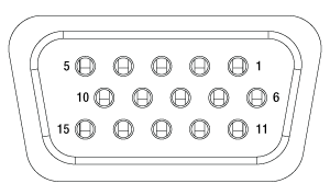
| Pin | Description | Pin | Description |
|---|---|---|---|
| 1 | 0 V | 9 | 0 V |
| 2 | OW-Aa | 10 | +5 V |
| 3 | OW-Ba | 11 | Limit Switch 3A/Encoder 3Ab |
| 4 | Limit Switch 1A/Encoder 1Ab | 12 | Limit Switch 3B/Encoder 3Bb |
| 5 | Limit Switch 1B/Encoder 1Bb | 13 | Limit Switch 4A/Encoder 4Ab |
| 6 | Limit Switch 2A/Encoder 2Ab | 14 | Limit Switch 4B/Encoder 4Bb |
| 7 | Limit Switch 2B/Encoder 2Bb | 15 | OW-Da |
| 8 | OW-Ca | - | - |
CH-A, CH-B
SMA Female

-10 V to +10 V Input
Used to connect an external analog signal source to control the position of the actuator. The input voltage range is -10 V to +10 V, where -10 V provides max backwards velocity and +10 V provides max forward velocity. 0 V results in no movement. The input impedance is 100 kΩ.
I/O 1, I/O 2
SMA Female

+5 V TTL
These connectors provide a 5 V logic level input and output that can be configured to support triggering into and out of external devices. Each port can be independently configured to control the logic level or to set the trigger as an input or output.
K-Cube Mounting
Each K-Cube unit comes with a mounting plate that clips onto the base of the controller, as shown in the animation below. The plate contains two magnets for temporary placement on an optical table and two counterbores for 1/4"-20 (M6) cap screws for a more permanent placement on the tabletop.
K-Cube Table Mounting Plate
Thorlabs offers two platforms to drive our wide range of motion controllers: our Kinesis® software package or the legacy APT™ (Advanced Positioning Technology) software package. Either package can be used to control devices in the Kinesis family, which covers a wide range of motion controllers ranging from small, low-powered, single-channel drivers (such as the K-Cubes™ and T-Cubes™) to high-power, multi-channel, modular 19" rack nanopositioning systems (the APT Rack System).
The Kinesis Software features .NET controls which can be used by 3rd party developers working in the latest C#, Visual Basic, LabVIEW™, or any .NET compatible languages to create custom applications. Low-level DLL libraries are included for applications not expected to use the .NET framework. A Central Sequence Manager supports integration and synchronization of all Thorlabs motion control hardware.

Kinesis GUI Screen
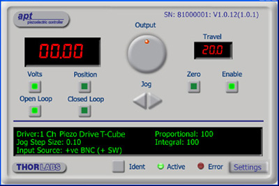
APT GUI Screen
Our legacy APT System Software platform offers ActiveX-based controls which can be used by 3rd party developers working on C#, Visual Basic, LabVIEW™, or any Active-X compatible languages to create custom applications and includes a simulator mode to assist in developing custom applications without requiring hardware.
By providing these common software platforms, Thorlabs has ensured that users can easily mix and match any of the Kinesis and APT controllers in a single application, while only having to learn a single set of software tools. In this way, it is perfectly feasible to combine any of the controllers from single-axis to multi-axis systems and control all from a single, PC-based unified software interface.
The software packages allow two methods of usage: graphical user interface (GUI) utilities for direct interaction with and control of the controllers 'out of the box', and a set of programming interfaces that allow custom-integrated positioning and alignment solutions to be easily programmed in the development language of choice.
A range of video tutorials is available to help explain our APT system software. These tutorials provide an overview of the software and the APT Config utility. Additionally, a tutorial video is available to explain how to select simulator mode within the software, which allows the user to experiment with the software without a controller connected. Please select the APT Tutorials tab above to view these videos.
Software
Kinesis Version 1.14.49
The Kinesis Software Package, which includes a GUI for control of Thorlabs' Kinesis and APT™ system controllers.
Also Available:
- Communications Protocol
Thorlabs' Kinesis® software features new .NET controls which can be used by third-party developers working in the latest C#, Visual Basic, LabVIEW™, or any .NET compatible languages to create custom applications.
C#
This programming language is designed to allow multiple programming paradigms, or languages, to be used, thus allowing for complex problems to be solved in an easy or efficient manner. It encompasses typing, imperative, declarative, functional, generic, object-oriented, and component-oriented programming. By providing functionality with this common software platform, Thorlabs has ensured that users can easily mix and match any of the Kinesis controllers in a single application, while only having to learn a single set of software tools. In this way, it is perfectly feasible to combine any of the controllers from the low-powered, single-axis to the high-powered, multi-axis systems and control all from a single, PC-based unified software interface.
The Kinesis System Software allows two methods of usage: graphical user interface (GUI) utilities for direct interaction and control of the controllers 'out of the box', and a set of programming interfaces that allow custom-integrated positioning and alignment solutions to be easily programmed in the development language of choice.
For a collection of example projects that can be compiled and run to demonstrate the different ways in which developers can build on the Kinesis motion control libraries, click on the links below. Please note that a separate integrated development environment (IDE) (e.g., Microsoft Visual Studio) will be required to execute the Quick Start examples. The C# example projects can be executed using the included .NET controls in the Kinesis software package (see the Kinesis Software tab for details).
 |
Click Here for the Kinesis with C# Quick Start Guide Click Here for C# Example Projects Click Here for Quick Start Device Control Examples |
 |
LabVIEW
LabVIEW can be used to communicate with any Kinesis- or APT-based controller via .NET controls. In LabVIEW, you build a user interface, known as a front panel, with a set of tools and objects and then add code using graphical representations of functions to control the front panel objects. The LabVIEW tutorial, provided below, provides some information on using the .NET controls to create control GUIs for Kinesis- and APT-driven devices within LabVIEW. It includes an overview with basic information about using controllers in LabVIEW and explains the setup procedure that needs to be completed before using a LabVIEW GUI to operate a device.
 |
Click Here to View the LabVIEW Guide Click Here to View the Kinesis with LabVIEW Overview Page |
 |
The APT video tutorials available here fall into two main groups - one group covers using the supplied APT utilities and the second group covers programming the APT System using a selection of different programming environments.
Disclaimer: The videos below were originally produced in Adobe Flash. Following the discontinuation of Flash after 2020, these tutorials were re-recorded for future use. The Flash Player controls still appear in the bottom of each video, but they are not functional.
Every APT controller is supplied with the utilities APTUser and APTConfig. APTUser provides a quick and easy way of interacting with the APT control hardware using intuitive graphical control panels. APTConfig is an 'off-line' utility that allows various system wide settings to be made such as pre-selecting mechanical stage types and associating them with specific motion controllers.
APT User Utility
The first video below gives an overview of using the APTUser Utility. The OptoDriver single channel controller products can be operated via their front panel controls in the absence of a control PC. The stored settings relating to the operation of these front panel controls can be changed using the APTUser utility. The second video illustrates this process.
APT Config Utility
There are various APT system-wide settings that can be made using the APT Config utility, including setting up a simulated hardware configuration and associating mechanical stages with specific motor drive channels. The first video presents a brief overview of the APT Config application. More details on creating a simulated hardware configuration and making stage associations are present in the next two videos.
APT Programming
The APT Software System is implemented as a collection of ActiveX Controls. ActiveX Controls are language-independant software modules that provide both a graphical user interface and a programming interface. There is an ActiveX Control type for each type of hardware unit, e.g. a Motor ActiveX Control covers operation with any type of APT motor controller (DC or stepper). Many Windows software development environments and languages directly support ActiveX Controls, and, once such a Control is embedded into a custom application, all of the functionality it contains is immediately available to the application for automated operation. The videos below illustrate the basics of using the APT ActiveX Controls with LabVIEW, Visual Basic, and Visual C++. Note that many other languages support ActiveX including LabWindows CVI, C++ Builder, VB.NET, C#.NET, Office VBA, Matlab, HPVEE etc. Although these environments are not covered specifically by the tutorial videos, many of the ideas shown will still be relevant to using these other languages.
Visual Basic
Part 1 illustrates how to get an APT ActiveX Control running within Visual Basic, and Part 2 goes on to show how to program a custom positioning sequence.
LabVIEW
Full Active support is provided by LabVIEW and the series of tutorial videos below illustrate the basic building blocks in creating a custom APT motion control sequence. We start by showing how to call up the Thorlabs-supplied online help during software development. Part 2 illustrates how to create an APT ActiveX Control. ActiveX Controls provide both Methods (i.e. Functions) and Properties (i.e. Value Settings). Parts 3 and 4 show how to create and wire up both the methods and properties exposed by an ActiveX Control. Finally, in Part 5, we pull everything together and show a completed LabVIEW example program that demonstrates a custom move sequence.
Part 1: Accessing Online Help
Part 2: Creating an ActiveX Control
Part 3: Create an ActiveX Method
Part 4: Create an ActiveX Property
Part 5: How to Start an ActiveX Control
The following tutorial videos illustrate alternative ways of creating Method and Property nodes:
Create an ActiveX Method (Alternative)
Create an ActiveX Property (Alternative)
Visual C++
Part 1 illustrates how to get an APT ActiveX Control running within Visual C++, and Part 2 goes on to show how to program a custom positioning sequence.
MATLAB
For assistance when using MATLAB and ActiveX controls with the Thorlabs APT positioners, click here.
To further assist programmers, a guide to programming the APT software in LabVIEW is also available here.
| Posted Comments: | |
do'neill
(posted 2024-08-27 04:40:28.0) Thank you for your comment. You can get this to move to specific positions with the command device.MoveTo(). I will reach out to you directly to discuss your application with you. Nate Kimmitt
(posted 2023-11-10 10:20:47.223) Hi,
I'm trying to control the KIM101 in Matlab. Is there an example you could provide for me?
Thanks,
Nate do'neill
(posted 2023-11-13 07:29:43.0) Feedback from Daniel at Thorlabs. I will reach out to you directly to provide this example. Jim Cordova
(posted 2023-11-01 15:22:45.07) Does the KIM101 have built-in protection to protect the piezo motor on an active stage if it runs into a mechanical hard stop?
Or, is the piezo motor immune to such damage?
Thanks,
Jim do'neill
(posted 2023-11-13 06:26:24.0) Response from Daniel at Thorlabs. Our piezo inertia actuators do not have feedback to allow for our KIM101 to tell it has reached the limit. It would be possible for the user, using a 3rd partly software/language, to create a software form of a limit switch if something is added to the application to provide this feedback.
Also, the PIAs, due to the slip stick design, do not have an issue being over driven as the leadscrew will just not move. This is not an issue as long as this is only for a short period. Continuous overdriving past the limit for prolonged periods will cause wear and damage to the mechanism. Da Lieshout
(posted 2023-10-05 07:12:40.663) Ah, for the COM-port had to right click on the ATP USB, Advanced and check the box of "Load VCP" (that is Virtual Com Port). Case closed. do'neill
(posted 2023-10-10 10:30:44.0) Response from Daniel at Thorlabs. Glad to hear this is resolved, don't hesitate to reach out if you have further issues. Da Li
(posted 2023-10-04 12:31:48.323) Have a KIM101 working on older laptop.
Have to install on a new laptop. Old an new has installed the x64 software.
After install ATP and Kinesis we do not see a COM-port in the Windows Device Manager. What could be wrong. Is there another driver available? user
(posted 2023-09-25 14:14:19.177) Hi, could you please help me? I am continuously obtaining this error message in LabView:
Expected Assembly "Thorlabs.MotionControl.Controls, Version=1.14.12.0, Culture=neutral, PublicKeyToken=c7ec6d6d6e2435e7", but found "Thorlabs.MotionControl.Controls, Version=1.14.37.21486, Culture=neutral, PublicKeyToken=c7ec6d6d6e2435e7."
I used to work with different types of KCube motors and everything works well. However, I am unable to control the Piezo Motor Controller in LabView. do'neill
(posted 2023-09-27 10:25:39.0) Response from Daniel at Thorlabs. I will reach out to you directly to help troubleshoot this to find where the error might be coming from and help you with fixing it. junyeop kim
(posted 2023-08-09 14:23:31.92) I'm trying to connect with KIM101 using MATLAB.
I succeeded in conncet to KIM101. But it failed to find channel1 via InertialMotorStatus. (I approached it the same way as the python example you provided.)
Looking at the previous comments, it seems that there is already an example provided.
If possible, can I get a MATLAB example for KIM101? do'neill
(posted 2023-08-09 10:46:12.0) Response from Daniel at Thorlabs. I will reach out to directly with an example for this. TaiBei Liu
(posted 2023-07-04 20:01:52.697) Can you provide me with a document about my own programming operations?C# or labelview or c++ or matlab... fguzman
(posted 2023-07-06 10:52:26.0) Thanks for your enquiry. For this item we have some guidelines in our website https://www.thorlabs.de/newgrouppage9.cfm?objectgroup_id=9790&pn=KIM001&tabname=Kinesis%20Tutorials
Also, our Kinesis software features .NET controls which can be used by 3rd party developers working in C#, LabVIEW etc. There is also low-level DLL libraries included for applications not expected to use the .NET framework. We have several examples in our GitHub page: https://github.com/thorlabs Nadav Frenkel
(posted 2023-05-18 23:21:37.087) Im trying to establish a connection with KIM101 using MATLAB.
I'm using a code (attached below) provided by Thorlabs that uses the DLLs found in the Kinesis folder and I'm using DotNet_API to alter the command to be correct specifically to KIM101.
However, I'm having a hard time connecting to the device and understanding what are basic commands needed to establish the connection.
Moreover, if the connection for some reason fails, I am no longer able to connect to the device (meaning, passing the "connect" line successfully) without turning it OFF and ON back.
Are you aware of such problems? do you have any suggestions on what can I do differently?
Code:
%You can use the Kinesis .NET dll library in Matlab to control the stages.
% After download and install of Kinesis Thorlabs - Your Source for Fiber Optics, Laser Diodes, Optical Instrumentation and Polarization Measurement & Control.
% you can find the dll files in the folder C:\Program Files\Thorlabs\Kinesis
% The DotNet_API help file is also in this folder.
% I send you a Matlab code example for the KDC101 controller in the attachment.
%Example for programming the Thorlabs KDC101 with Kinesis in MATLAB, with PRM1-Z8 stage.
clear all
%Load assemblies
NET.addAssembly('C:\Program Files\Thorlabs\Kinesis\Thorlabs.MotionControl.DeviceManagerCLI.dll');
% NET.addAssembly('C:\Program Files\Thorlabs\Kinesis\Thorlabs.MotionControl.GenericMotorCLI.dll');
% NET.addAssembly('C:\Program Files\Thorlabs\Kinesis\Thorlabs.MotionControl.KCube.DCServoCLI.dll');
NET.addAssembly('C:\Program Files\Thorlabs\Kinesis\Thorlabs.MotionControl.KCube.InertialMotorCLI.dll');
% NET.addAssembly('C:\Program Files\Thorlabs\Kinesis\Thorlabs.MotionControl.KCube.InertialMotor.dll');
% NET.addAssembly('C:\Program Files\Thorlabs\Kinesis\Thorlabs.MotionControl.DeviceManager.dll');
%Initialize Device List
import Thorlabs.MotionControl.DeviceManagerCLI.*
% import Thorlabs.MotionControl.GenericMotorCLI.*
% import Thorlabs.MotionControl.KCube.DCServoCLI.*
import Thorlabs.MotionControl.KCube.InertialMotorCLI.*
%% Create Simulation
% SimulationManager.Instance.InitializeSimulations();
%Initialize Device List
try
DeviceManagerCLI.BuildDeviceList();
DeviceManagerCLI.GetDeviceListSize();
%Should change the serial number below to the one being used.
serial_num='97102270';
timeout_val=60000;
%Set up device and configuration
device = KCubeInertialMotor.CreateKCubeInertialMotor(serial_num);
device.Connect(serial_num);
device.WaitForSettingsInitialized(5000);
deviceInfo = device.GetDeviceInfo();
% configure the stage
motorSettings = device.GetInertialMotorConfiguration(serial_num);
motorSettings.DeviceSettingsName = 'KIM101';
% update the RealToDeviceUnit converter
motorSettings.UpdateCurrentConfiguration();
% push the settings down to the device
MotorDeviceSettings = device.MotorDeviceSettings;
device.SetSettings(MotorDeviceSettings, true, false);
device.StartPolling(250);
pause(1); %wait to make sure device is enabled
%Home
device.Home(timeout_val);
fprintf('Motor homed.\n');
%Move to unit 100
device.MoveTo(100, timeout_val);
%Check Position
pos = System.Decimal.ToDouble(device.Position);
fprintf('The motor position is %d.\n',pos);
device.StopPolling()
device.Disconnect()
catch
disp('error')
device.Disconnect()
end do'neill
(posted 2023-05-19 07:01:59.0) Response from Daniel at Thorlabs. I will reach out to you directly to discuss this with you and help you with your application and provide you an example for controlling the KIM101 in MATLAB. Adam Smith
(posted 2023-01-20 17:17:39.017) Hi, Is it possible to control the KIM101 using a separate ic or arduino or any other way not through the software. To clarify, can i just drive the control signals myself or does it have to be through the software.
Thanks JReeder
(posted 2023-01-24 04:41:41.0) Thanks for your enquiry. Our Kinesis software features .NET controls which can be used by 3rd party developers working in C#, LabVIEW etc. There is also low-level DLL libraries included for applications not expected to use the .NET framework. We have several examples in our GitHub page: https://github.com/thorlabs. There is also the option to use serial commands with theses devices, the communications protocol can be found here: https://www.thorlabs.com/software_pages/ViewSoftwarePage.cfm?Code=Motion_Control&viewtab=2. If you are looking to only drive this using an external voltage source there is an External input SMA which accepts -10 V to +10 V. I have reached out to you to discuss your application further. user
(posted 2022-08-24 12:05:58.607) Hi,
When I looked through the details about the KIM101, I couldn't find out the specification of output current from each channel.
Can you let me know any information about that (Ex: The maximum output current from each channel, or the range of the output current )?
Thanks a lot. DJayasuriya
(posted 2022-08-24 07:01:02.0) Thank you for your inquiry. This would have couple of things to consider; the output driver is designed specifically for our PIAs within a certain range of capacitance and output driver is totally non-linear and is made up of two separate parts. We have got in touch with more details. Théo Geral
(posted 2022-04-19 13:10:26.227) Hello,
I'm looking for python help controlling the KIM101. I saw that you already send some exemples to other users. Could you send them to me please ? Thank you. cwright
(posted 2022-04-21 08:38:26.0) Response from Charles at Thorlabs: Thank you for your query. Python is not a language which we can officially support but we do have a couple of examples. I will reach out to you with one for the KIM101. Juan sebastian Leon. Rodriguez
(posted 2022-02-23 20:57:35.0) What kind of license do you use for the API provided by you, both in C++ and C# for the use and creation of programs that control the KIM101 device created by you, are the dll's open source or is it under some kind of paid licensing for its use? DJayasuriya
(posted 2022-02-24 10:58:05.0) Thank you for your inquiry, The dll's can be found when you download our software, it is not under any paid licensing. Similarly communications protocol can be found on our website : https://www.thorlabs.com/Software/Motion%20Control/APT_Communications_Protocol.pdf user
(posted 2021-11-10 00:51:52.6) Hi, I am trying to control KIM101 using C# example "KPZ_KCubePiezoController " under "Quick Start Device Control Examples" but I always connect failed.I get error message below:
"Unable to connect to device
Thorlabs.MotionControl.DeviceManagerCLI.DeviceNotReadyException: Device is not connected"
Could you send me some examples of KIM101. Thank you. cwright
(posted 2021-11-10 05:21:00.0) Response from Charles at THorlabs: Thank you for your query. The example you refer to is for simple piezo controllers. The KIM controlls what we term "Piezo Motors" as they operate very differently than a typical piezo. I will reach out to you with an example. user
(posted 2021-08-10 10:36:18.267) I am looking to set up a closed loop system with the KIM101 and was looking to receive some guidance as I cannot figure out if the KIM101 supports a closed loop system. cwright
(posted 2021-08-18 04:39:01.0) Response from Charles at Thorlabs: Thank you for your query. Feedback from the KPA101 can be used in conjunction with the KIM101 CH-A, CH-B inputs for a closed loop system which maintains the system on a point. The limit/encoder pins are for future use as we develop PIA’s with feedback, though they can be used as limit switches. I will reach out to you to discuss your application. Michael Pfeiffer-Härtl
(posted 2021-01-26 01:24:27.887) Hello,
is there a specification available which describes the programming interface/control commands of these controllers? The idea is to use the out of an own application but not with the software you recommend. DJayasuriya
(posted 2021-01-27 03:43:35.0) Thank you for your inquiry. Yes, we do provide the.dll files(some assemblies are .NET dlls and some are Native C dlls) with the software download. You will also have access to the .NET API Help document (file path C:\Program
Files\Thorlabs\Kinesis\Thorlabs.MotionControl.DotNet_API).
Please have a look at the our communication protocol for low level communication protocol: https://www.thorlabs.de/Software/Motion%20Control/APT_Communications_Protocol.pdf
Hope this helps. If you have any questions, do not hesitate to get in touch with your local tech support team, who would be happy to help. Peter Coffell
(posted 2020-11-14 16:46:47.63) Hello,
I was wondering if he KIN 101 can control brushed motors also? cwright
(posted 2020-11-17 05:37:35.0) Response from Charles at Thorlabs: Hello and thank you for your query. This controller is not intended to be used to control DC motors and has no settings to facilitate this. Further, the voltage it outputs is a sawtooth waveform which can only be adjusted from 85 - 125V. The motor would see an averaged but high voltage which would damage the motor. We recommend the KDC101 to control brushed dc motors. D W
(posted 2020-11-05 04:52:16.697) Is there any way to determine when the KIM device has finished moving using the C API?
The documentation hints that this might be possible using KIM_WaitForMessage (at least for different types of motors), however it doesn't seem to emit anything when it's finished moving. The messages it occassionally emits while moving (messageType==12, messageID==0) are completely undocumented.
The "status bits" (e.g. KIM_GetStatusBits()) look like they might also be relevant, but the output is also undocumented. cwright
(posted 2020-11-06 09:07:44.0) Response from Charles at Thorlabs: thank you for your query. It appears that our documentation may be lacking some updates relevant to the KIM. We will look into this and contact you directly to follow up. Ari Feldman
(posted 2020-09-28 18:30:01.243) Looking for python help controlling the KIM101. Others have received examples on how to interface the dll with ctypes. Could you also share with me? DJayasuriya
(posted 2020-10-06 03:42:21.0) Thank you for your inquiry. Yes of course, we will get in touch with you directly with an example python code and to discus your application. user
(posted 2020-04-27 03:04:54.54) Hello, is it possible to control KIM001 with Matlab appdesigner? DJayasuriya
(posted 2020-04-27 10:55:27.0) Response from Dinuka at Thorlabs: Thank you for your inquiry at the moment we would not be able to directly support MATLAB app designer, but I will get in touch with you directly to see if we can help with your application. Joseph Natal
(posted 2020-02-17 00:05:04.76) Hi. I'm wondering if these K-Cube or T-cube controllers could be useful for vibration damping applications. I'm thinking I may purchase the high voltage piezo amplifier to use with a controller I make myself, incorporating a third party position sensing device for active feedback. The project is to create my own controller, so I figure I should just purchase the amplifier. This would be for a UC Berkeley course with possible application Lawrence Berkeley National Lab, where I work at the BELLA center.
Thanks,
Joe DJayasuriya
(posted 2020-02-19 04:09:02.0) Response from Dinuka at Thorlabs: Hello Joe, Thank you for contacting us. It seems like you are trying to use the cube for active vibrational damping. The K cube or T cube controllers would not be able to achieve what you are looking for. However I will get in touch with you directly to discuss your application. user
(posted 2020-01-10 07:55:11.823) Just to explain a bit further about the symptom of the problem with KIM101 after the firmware update.. After the firmware update, I can see the USB Device Node on the FirmwareUpdateUtility, but it does not show any controller that can/cannot be reprogrammed. So I cannot Flash Firmware again nor control the piezo inertia stage (PD1) How can I solve this problem? cwright
(posted 2020-01-22 04:24:54.0) Response from Charles at Thorlabs: thank you for contacting us about this. It appears that your firmware has been corrupted. This is most likely caused by a loss of power to the device during reprogramming. This may be something which can be quickly fixed at the users end or it may be necessary for us to reprogram it at one of our offices. I will reach out to you directly to troubleshoot this. user
(posted 2020-01-10 05:42:42.8) We have recently purchased KIM101 (to control PD1 stages). Initially it was possible to control it with the APTUser software on a computer. But after I accidentally updated the firmware using the Thorlabs FirmwareUpdateUtility, the device (KIM101) is not even recognized by the computer. Could you please help me regarding this? Alan Blair
(posted 2019-05-22 12:19:27.563) We would like to embed this in a device which will be remotely controlled. Can you tell me how the power switch is connected so we can make a remote circuit to emulate it? Alternatively, there is a connector on the bottom of the KIM101. Can this be used to control the on/off functionality? AManickavasagam
(posted 2019-05-28 05:11:29.0) Response from Arunthathi at Thorlabs: Thanks for your query. I have contacted you directly with the details of the power switch connection and feasibility of controlling the KIM101 remotely along with the circuit diagram for your reference. e.lopez
(posted 2018-11-23 08:22:36.45) Can this controller be controlled by Matlab?
Thank you,
Eneko rmiron
(posted 2018-11-23 04:00:04.0) Response from Radu at Thorlabs: There are multiple paths for controlling KIM101 from MATLAB. One would be to use the ActiveX controls that come with APT, our legacy software. We have a short guide on how to get started. You can download it via this link: https://www.thorlabs.com/tutorials/Thorlabs_APT_MATLAB.docx
A second option would be to bypass our software and send serial commands directly from MATLAB to the device. You can find the documentation for our serial communications protocol here: https://www.thorlabs.com/Software/Motion%20Control/APT_Communications_Protocol.pdf
Finally, our .NET API for Kinesis can be used from MATLAB, but we don't have any guides or examples that can help you get started. I should mention that the API is composed of .NET assemblies, as opposed to COM DLLs. michael.nickerson
(posted 2017-10-18 11:10:29.133) This TIM101 would be far more useful if it could be controlled by the KPA101 or other KCH-mountable controllers, instead of manual control only. AManickavasagam
(posted 2017-10-27 11:36:06.0) Response from Arunthathi at Thorlabs: Thank you for your query. Unfortunately, without external electronics there is no way to control TIM101 with KPA101 for beam stabilisation/tracking.
We will note this requirement and notify our engineers. user
(posted 2017-07-11 15:02:32.83) Can this controller be controlled by a Python script ? I've found some modules online (thorlabs_apt and PyAPT), but they don't seem to be working with TIM101. I'm trying to send it instructions depending on some data returned by a Python program, in order to calibrate the position of a laser beam with two piezo inertia actuators mounted on a mirror. bhallewell
(posted 2017-07-13 09:36:41.0) Response from Ben at Thorlabs: Unfortunately we do not support use of APT through Python. What we do have available is a number of videos & guides found in the following webpage for Visual Studio (Basic & C++) & LabVIEW.
We also hold examples for programming in our latest motion control software, Kinesis, through LabVIEW & Visual Studio (C# & C) environments.
https://www.thorlabs.com/navigation.cfm?guide_id=2251 peebles
(posted 2016-07-19 12:54:47.94) Does the controller allow you to set a specific distance of translation when coupled with a suitable piezo transducer and translation stage.
If so what would be the accuracy of the final distance moved e.g. If asked to move the translation stage 1 cm, how accurate would be the final movement?
Also is there any sort of readout of position ?
Thanks, Tony Peebles
Our application requires ~2cm movement of a plastic lens weighing about 2 pounds in both horizontal and vertical directions. bwood
(posted 2016-07-20 03:54:37.0) Response from Ben at Thorlabs: Thank you for your question. The TIM101 cannot provide the position of the actuator in meters, due to the varying step size it can only output the number of steps. Furthermore, the TIM101 cannot currently be coupled with an external feedback mechanism, to calculate the position within the controller and our motion control software hemselves. One potential solution would be to use an external feedback mechanism to measure the position, and to generate a control signal to the analogue input of the TIM101 to move the actuator to a given position. This would create a closed loop system, similar to a conventional closed loop piezo system. |

| Key Specificationsa | ||
|---|---|---|
| Item # | KIM001 | KIM101 |
| Piezoelectric Outputs (SMC Male) | One | Four |
| Piezo Output Voltage | 85 to 125 VDC | 85 to 125 VDC per Channel |
| Top Panel Controls | Scroll Wheel | Dual-Axis Joystick |
| External Input (SMA Female) |
±10 V ± 2% | |
| Input Power | +15 VDC @ 2 A | |
| Housing Dimensionsb |
60.0 mm x 60.0 mm x 47.0 mm (2.36" x 2.36" x 1.85") |
121.0 mm x 60.0 mm x 47.0 mm (4.76" x 2.36" x 1.85") |
| Compatible Software | Kinesis & Legacy APT | |
- Top Panel Controls and Display Screen for Standalone Operation
- USB Connectivity for 'Plug-and-Play' PC Control
- Adjustable Voltage Output from 85 V to 125 V
- Power Supply Not Included (Available Below)
These compact K-Cube Controllers provide easy manual and PC control of our piezo inertia stages, actuators, and optic mounts. They feature adjustable voltage output from 85 V to 125 V. The top panel display screen enables operation as soon as the unit is turned on, without the need for connection to a PC. Alternatively, both controllers have USB connectivity that provides 'Plug-and-Play' PC-controlled operation with our Kinesis® software package (included). These controllers can also be operated with our legacy APT™ (Advanced Positioning Technology) software package.
Please note that these controllers do not ship with a power supply. The compatible KPS201 power supply is sold below.
KIM001 Single-Channel Controller
This single-channel piezo inertia controller provides a voltage output for a single piezo inertia stage or actuator. The top panel features a spring-loaded scroll wheel for driving the stage or actuator as well as selecting menu options.
KIM101 Four-Channel Controller
This four-channel controller features four SMC outputs to drive piezo inertia devices. The channels can be controlled independently or simultaneously in pairs using the dual-axis joystick on the controller's top panel. The controller can be configured to operate up to four PD series piezo inertia stages, up to four PIA seies piezo inertia actuators, or up to two PIM series piezo inertia optic mounts; one KIM101 can only concurrently drive devices that use the same "Select Stage" configuration in the controller's menu options (see the manuals for more details).

- Power Supply Compatible with KIM001 and KIM101 Motor Controllers
- Universal Input: 100 - 240 VAC
- Region-Specific Adapter Plug Shipped with Power Supply
The KPS201 power supply outputs +15 VDC at up to 2.66 A and can power a single K-Cube or T-Cube with a 3.5 mm jack. It plugs into a standard wall outlet. One region-specific plug adapter, selectable at checkout, is included with each power supply.
 Products Home


 Zoom
Zoom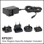
 K-Cube Piezo Inertia Actuator Controllers