Manual Rotation Mounts, High Precision
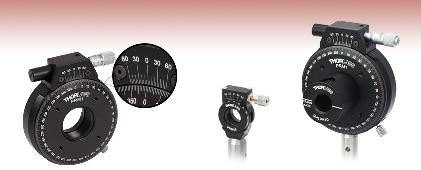
- Continuous 360° Rotation
- Fully Compatible with Our Lens Tubes and Accessories
- Ideal for Ø1/2", Ø1", or Ø2" Polarization Optics
Laser-Engraved
Vernier Scale
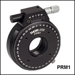
PRM1
Precision
Rotation Mount
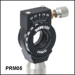
PRM05
Post Not Included
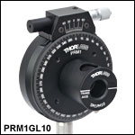
PRM1 Precision
Rotation Mount with
SM1PM10 Prism
Mounting Hardware
Also Available for
PRM05, See Below
Application Idea

Please Wait
Features
- Manual High-Precision Rotation Mounts for Ø1/2", Ø1", or Ø2" Optics
- 360° of Continuous Coarse Rotation
- Fine Rotation over ±7° Rotation Dial is Locked
- Vernier Scale with Two Resolution Options
- 10 arcmin (PRM05 and PRM05GL5)
- 5 arcmin (PRM1, PRM1GL10, and PRM2)
- Fully Compatible with Our Lens Tubes
- Motorized Rotation Mount also Available
These high-precision rotation mounts combine 360° of coarse manual rotation with precise, backlash-free fine adjustment. These mounts are compatible with Ø1/2", Ø1", or Ø2" optics, as well as Thorlabs' SM05 (0.535"-40), SM1 (1.035"-40), or SM2 (2.035"-40) lens tubes, respectively. The PRM1 and PRM2 Ø1" and Ø2" mounts are also compatible with our cage systems. The 30 mm cage system can be attached to the PRM1, and the 60 mm cage system can be attached to the PRM2.
The rotation dial features a laser-engraved scale, a knurled edge for smooth coarse rotation, and a locking mechanism. When the locking mechanism is engaged, the mount's rotation can then be adjusted via a fine drive adjuster located at the top of the mount (see below for item-specific rotation and locking information). These rotation mounts can be secured to our Ø1/2" posts via a bottom-located 8-32 (M4) tapped hole.
Please see the Rotation Mounts and Stages tab for our entire selection of rotation mounts and stages.
Reading a Vernier Scale on a Linear Main Scale
Vernier scales are typically used to add precision to standard, evenly divided scales (such as the scales on Thorlabs' rotation, goniometric, or translation mounts). A vernier scale has found common use in many precision measurement instruments, the most common being calipers and micrometers. The vernier scale uses two scales side-by-side: the main scale and the vernier scale. The direct vernier scale has a slightly smaller spacing between its tick marks owing to the vernier scale having N ticks for every N - 1 ticks on the main scale. Hence, the lines on the main scale will not line up with all the lines on the vernier scale. Only one line from the vernier scale will match well with one line of the main scale, and that is the trick to reading a vernier scale.
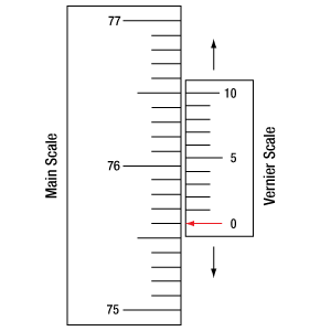
Figures 130A through 130C show a linear vernier scale system for three different situations. In each case, the scale on the left is the main scale, while the small scale on the right is the vernier scale. When reading a vernier scale, the main scale is used for the gross number, and the vernier scale gives the precision value. In this manner, a standard ruler or micrometer can become a precision instrument.
The 0 on the vernier scale is the "pointer" (marked by a red arrow in Figures 130A through 130E) and will indicate the main scale reading. In Figure 130A we see the pointer is lined up directly with the 75.6 line. Notice that the only other vernier scale tick mark that lines up well with the main scale is 10. Since the pointer lines up with the main scale’s 75.6, the reading from Figure 130A is 75.60 (in whatever units the instrument measures).
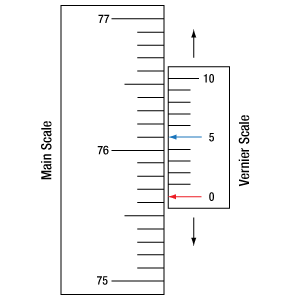
That is essentially all there is to reading a vernier scale. It's a very straightforward way of increasing the precision of a measurement instrument. To expound, let’s look at Figure 130B. Here we see that the pointer is no longer aligned with a line on the main scale, but instead it is slightly above 75.6 and below 75.7; thus, the gross measurement is 75.6. The first vernier line that coincides with a main scale line is the 5, shown with a blue arrow. The vernier scale gives the final digit of precision; since the 5 is aligned to the main scale, the precision measurement for Figure 130B is 75.65.
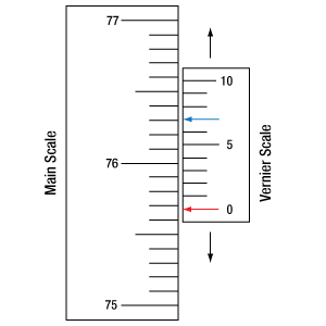
Since this vernier scale is 10% smaller than the main scale, moving the vernier scale by 1/10 of the main scale will align the next vernier marking. This asks the obvious question: what if the measurement is within the 1/10 precision of the vernier scale? Figure 130C shows just this. Again, the pointer line is in between 75.6 and 75.7, yielding the gross measurement of 75.6. If we look closely, we see that the vernier scale 7 (marked with a blue arrow) is very closely aligned to the main scale, giving a precision measurement of 75.67. However, the vernier scale 7 is very slightly above the main scale mark, and we can see that the vernier scale 8 (directly above 7) is slightly below its corresponding main scale mark. Hence, the scale on Figure 130C could be read as 75.673 ± 0.002. A reading error of about 0.002 would be appropriate for
this instrument.
Click to Enlarge
Figure 130A An example of how to read a vernier scale. The red arrow indicates what is known as the pointer. Since the tick mark labeled 10 on the vernier scale aligns with one of the tick marks on the main scale, this vernier scale is reading 75.60 (in whatever units the instrument measures).
Click to Enlarge
Figure 130B The red arrow indicates the pointer and the blue arrow indicates the vernier line that matches the main scale. This scale reads 75.65.
Click to Enlarge
Figure 130C The red arrow indicates the pointer, and the blue arrow indicates the vernier line that matches the main scale. This scale reads 75.67 but can be accurately read as
75.673 ± 0.002.
Reading a Vernier Scale on a Rotating Main Scale
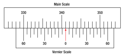
The vernier scale may also be used on rotating scales where the main scale and vernier scale do not share units. Figures 130D and 130F show a vernier scale system for two different situations where the main scale is given in degrees and the vernier scale has ticks every 5 arcmin (60 arcmin = 1°). In each case, the scale on the top is the main scale, while the small scale on the bottom is the vernier scale.
In Figure 130D we see the pointer is lined up directly with the 341° line. Notice that the only other vernier scale tick marks that line up well with the main scale are ±60 arcmin. Since the pointer lines up with the main scale at 341°, the reading from Figure 130D is 341.00°.
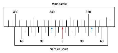
There are two ways to determine the reading if the zero on the vernier scale line is between two lines of the main scale. For the first method, take the line on the left side of the pointer on the vernier scale and subtract that value (in arcmin) from the value on the main scale that is to the right on the main scale. As an example, in Figure 130E the vernier pointer is between 342° and 343°; using the left blue arrow of the vernier scale results in
As we've seen here, vernier scales add precision to a standard scale measurement. While it takes a bit of getting used to, with a little practice, reading these scales is fairly straightforward. Vernier scales, whether they are direct or retrograde*, are read in the same fashion.
*A retrograde vernier scale has a larger spacing between its tick marks with N ticks for every N + 1 ticks on the main scale.
Click to Enlarge
Figure 130D An example of a vernier scale where the main scale and the vernier scale are in different units (degrees and arcmins, respectively). The red arrow indicates the pointer. This scale reads 341.00°.
Click to Enlarge
Figure 130E The red arrow indicates the pointer and the blue arrows give the precision value from the vernier scale.
This scale reads 342.75°.
| Posted Comments: | |
user
(posted 2021-07-14 05:02:39.57) I lost the 4-40 set screw for the PRM05/M precision mount. Do you know which of the set screws available at Thorlabs can be used to replace it? Thank you. YLohia
(posted 2021-07-15 11:03:48.0) Hello, we're sorry to hear that you've lost the component screw in the PRM05/M. The SS4N013 screw can be used to replace this. user
(posted 2018-01-02 18:44:55.69) The gap between the scale and vernier is too large to permit accurate reading, even when viewed at a glancing angle. tfrisch
(posted 2018-01-03 02:48:47.0) Thank you for contacting Thorlabs. I have posted your note in our internal engineering forum. Please reach out to us at TechSupport@Thorlabs.com if you would like to elaborate on your feedback. jacterry40
(posted 2017-03-23 14:33:41.75) I see you give a figure for resolution for the resolution of the PR1 of 2.4 arcmin. Do you have a similar figure for the PRM05? I'm not bothered about reading the scale, just interested in what the smallest angular movement is likely to be. Looking for around a mrad or better. jlow
(posted 2017-03-24 03:49:05.0) Response from Jeremy at Thorlabs: This is highly dependent on the person using the mount. An experienced person should be able to move a couple mrad easily. g.c
(posted 2015-07-16 14:38:18.89) We have one of your manual rotation mounts and for the life of me, I can't figure out if it's working properly. It is my understanding that, if I turn the micrometer head,it's suppose to rotate the graduated dial accordingly. In addition,the spring-loaded locking screw is quite strong and when I try sliding it,it doesn't do anything other than spring back; I can't get it to lock.Even if I did, is it suppose to engage the micrometer? If so, it ain't working.
At any rate, I'd appreciate if you could you could provide me with an instruction manual in PDF format so that students and I can be properly informed on how to use it withing damaging it.
Thanks George besembeson
(posted 2015-09-23 01:12:35.0) Response from Bweh at Thorlabs USA: The micrometer head is used for fine adjustment only after the locking screw is engaged. Once locked, the micrometer mechanism provides fine adjustment of locked platform. The slot on the locking screw provides the travel range for the fine adjustment so you should not forcefully slide that or stretch the spring as this will be returned. To use the stage, you manually rotate the mounting platform to desired orientation, lock that position (by screwing the locking knob clockwise), then use the micrometer for fine adjustment. Please feel free to call or contact me at techsupport@thorlabs.com if you need further clarification. drahmlow
(posted 2015-05-11 12:05:56.65) The PRM1GL10 specifically mentions being used with the Glan-Laser or Glan-Taylor polarizers; is there any reason it wouldn't work with a 10 mm PBS cube? cdaly
(posted 2015-05-12 03:47:03.0) Response from Chris at Thorlabs: Yes, the 10mm Glan Laser and Glan Taylor polarizers are in housings which make the items have an overall size of 15.9mm. The 10mm unmounted PBS cube would not fit securely in the mount. cdaly
(posted 2012-11-27 08:54:57.98) Response from Chris at Thorlabs: Thank you for using the feedback feature. The lowest profile rotation mount is going to be the nested optical mount, a combination of both LM1-A and LM1-B, which will give an overall thickness of just over 13 mm. As this is purely manual adjustment, you may want to instead consider using a 2" rotation mount with an SM2A6 adapter. The mount itself would still be of a thickness around 20 mm or so, but the clear aperture would be larger at 45 degrees. ian.craig
(posted 2012-11-15 12:32:52.947) I have been looking for, but unable to find, a low profile rotation stage. I have a nonlinear crystal in a 1" round mount that I need to be able to hit at an oblique angle while also being to rotate it to hit the optimum crystal orientation. The thinnest rotation mount I've been able to find has been about 16mm thick, and most are closer to 19mm. When trying to pass a beam through at 45 degrees, this leaves almost zero clear aperture. Is it possible to construct a low profile rotation mount that is 10mm thick or less (the thinner the better), more in line with the thickness of an LMR1? bdada
(posted 2012-02-02 19:25:00.0) Response from Buki at Thorlabs.com
Thank you for participating in our feedback forum. This request has come up before so I will check with our design team for a status update and post a response when I have more information.
Please contact TechSupport@thorlabs.com if you have any questions. alexandra.nemeth
(posted 2012-02-02 07:39:55.0) I would need a high precision rotation mount for Ø2" optics. Do you plan to launch such a product in the near future? jjurado
(posted 2011-07-14 14:58:00.0) Response from Javier at Thorlabs to wallon.nogueira: We offer a variety of gimbal mounts which are designed to allow rotation of an optic about a point. These mounts feature different adjustment ranges, as well as different body types: http://www.thorlabs.com/NewGroupPage9.cfm?ObjectGroup_ID=2857
I will contact you directly for further assistance. wallon.nogueira
(posted 2011-07-13 17:57:21.0) Dear Sr(a).
Is there a rotation mount that allows also the control of the horizontal and vertical angles?
Thank you in advance.
Best regards,
Wallon Tyler
(posted 2008-09-30 12:20:08.0) A response from Tyler at Thorlabs to acable: The pictures on this page have been reshot to maximize their clarity. In addition, the picture of each part on our product page (click on the hyperlinked part number in the table where the price is listed) can now be "zoomed" in on for a larger view. In addition, we can provide even larger resolution images of all of our products by request. Simply use this feedback form or email tech support a list of images that you would like to have. Thank you for taking the time to comment on the photographs on this page. acable
(posted 2007-12-17 19:37:47.0) It would be nice to have the PRM05 and PRM05GL5 photos that appear with the price boxes enlarged. In general, the large the photo, the easier they are to read and since we all depend a the photos to understand the product it would be great if a little more care would go into this part of the Thorlabs website. See the PRM1, that photo is fairly large, but by airbrushing out a little more post even this photo could be increased by 5%. Now compare the PRM1GL10, with the part number under the part the size of the photo is limited. |
Rotation Mount and Stage Selection Guide
Thorlabs offers a wide variety of manual and motorized rotation mounts and stages. Rotation mounts are designed with an inner bore to mount a Ø1/2", Ø1", or Ø2" optic, while rotation stages are designed with mounting taps to attach a variety of components or systems. Motorized options are powered by a DC Servo motor, 2 phase stepper motor, piezo inertia motor, or an Elliptec™ resonant piezo motor. Each offers 360° of continuous rotation.
Manual Rotation Mounts
| Rotation Mounts for Ø1/2" Optics | |||||||
|---|---|---|---|---|---|---|---|
| Item # | MRM05(/M) | RSP05(/M) | CRM05 | PRM05(/M)a | SRM05 | KS05RS | CT104 |
| Click Photo to Enlarge |
 |
 |
 |
 |
 |
 |
 |
| Features | Mini Series | Standard | External SM1 (1.035"-40) Threads |
Micrometer | 16 mm Cage-Compatible | ±4° Kinematic Tip/Tilt Adjustment Plus Rotation | Compatible with 30 mm Cage Translation Stages and 1/4" Translation Stagesb |
| Additional Details | |||||||
| Rotation Mounts for Ø1" Optics | ||||||||
|---|---|---|---|---|---|---|---|---|
| Item # | RSP1(/M) | LRM1 | RSP1D(/M) | DLM1(/M) | CLR1(/M) | RSP1X15(/M) | RSP1X225(/M) | PRM1(/M)a |
| Click Photo to Enlarge |
 |
 |
 |
 |
 |
 |
 |
 |
| Features | Standard | External SM1 (1.035"-40) Threads |
Adjustable Zero | Two Independently Rotating Carriages | Rotates Optic Within Fixed Lens Tube System |
Continuous 360° Rotation or 15° Increments |
Continuous 360° Rotation or 22.5° Increments |
Micrometer |
| Additional Details | ||||||||
| Rotation Mounts for Ø1" Optics | ||||||
|---|---|---|---|---|---|---|
| Item # | LM1-A & LM1-B(/M) |
CRM1T(/M) | CRM1LT(/M) | CRM1PT(/M) | KS1RS | K6XS |
| Click Photo to Enlarge |
  |
 |
 |
 |
 |
 |
| Features | Optic Carriage Rotates Within Mounting Ring | 30 mm Cage-Compatiblea | 30 mm Cage-Compatible for Thick Opticsa |
30 mm Cage-Compatible with Micrometera |
±4° Kinematic Tip/Tilt Adjustment Plus Rotation | Six-Axis Kinematic Mounta |
| Additional Details | ||||||
| Rotation Mounts for Ø2" Optics | |||||||
|---|---|---|---|---|---|---|---|
| Item # | RSP2(/M) | RSP2D(/M) | PRM2(/M) | LM2-A & LM2-B(/M) |
LCRM2A(/M) | KS2RS | K6X2 |
| Click Photo to Enlarge |  |
 |
 |
  |
 |
 |
 |
| Features | Standard | Adjustable Zero |
Micrometer | Optic Carriage Rotates Within Mounting Ring | 60 mm Cage-Compatible | ±4° Kinematic Tip/Tilt Adjustment Plus Rotation | Six-Axis Kinematic Mount |
| Additional Details | |||||||
Manual Rotation Stages
| Manual Rotation Stages | ||||||
|---|---|---|---|---|---|---|
| Item # | RP005(/M) | PR005(/M) | MSRP01(/M) | RP01(/M) | RP03(/M) | QRP02(/M) |
| Click Photo to Enlarge |
 |
 |
 |
 |
 |
 |
| Features | Standard | Two Hard Stops | ||||
| Additional Details | ||||||
| Manual Rotation Stages | ||||||
|---|---|---|---|---|---|---|
| Item # | XRNR1(/M) | XRR1(/M) | PR01(/M) | CR1(/M) | XYR1(/M) | OCT-XYR1(/M) |
| Click Photo to Enlarge |
 |
 |
 |
 |
 |
 |
| Features | Fine Rotation Adjuster and 2" Wide Dovetail Quick Connect |
Fine Rotation Adjuster and 3" Wide Dovetail Quick Connect |
Fine Rotation Adjuster and SM1-Threaded Central Aperture |
Fine Pitch Worm Gear | Rotation and 1/2" Linear XY Translation | |
| Additional Details | ||||||
Motorized Rotation Mounts and Stages
| Motorized Rotation Mounts and Stages with Central Clear Apertures | |||||
|---|---|---|---|---|---|
| Item # | DDR25(/M) | PDR1C(/M) | PDR1(/M) | PDR1V(/M) | PDXR1(/M) |
| Click Photo to Enlarge |
 |
 |
 |
 |
 |
| Features | Compatible with SM05 Lens Tubes, 16 mm Cage System, & 30 mm Cage System |
Compatible with 16 mm Cage System |
Compatible with SM05 Lens Tubes & 30 mm Cage System |
Vacuum-Compatible; Also Compatible with SM05 Lens Tubes & 30 mm Cage System |
Compatible with SM05 Lens Tubes & 30 mm Cage System |
| Additional Details | |||||
| Motorized Rotation Mounts and Stages with Central Clear Apertures | |||||||
|---|---|---|---|---|---|---|---|
| Item # | K10CR1(/M) | PRM1Z8(/M)a | DDR100(/M) | ELL16 | ELL14 | ELL21(/M) | HDR50(/M) |
| Click Photo to Enlarge |
 |
 |
 |
 |
 |
 |
 |
| Features | Compatible with SM1 Lens Tubes & 30 mm Cage System | Compatible with SM1 Lens Tubes, 16 mm Cage System, 30 mm Cage System |
Compatible with SM05 Lens Tubes, Open Frame Design for OEM Applications |
Compatible with SM1 Lens Tubes, Open Frame Design for OEM Applications |
Compatible with SM2 Lens Tubes, Open Frame Design for OEM Applications |
Compatible with SM2 Lens Tubes |
|
| Additional Details | |||||||
| Motorized Rotation Mounts and Stages with Tapped Platforms | ||
|---|---|---|
| Item # | PRMTZ8(/M)a | ELL18(/M)b |
| Click Photo to Enlarge |
 |
 |
| Features | Tapped Mounting Platform for Mounting Prisms or Other Optics | Tapped Mounting Platform, Open Frame Design for OEM Applications |
| Additional Details | ||

Click for Details
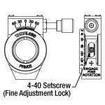
Figure 282A PRM05(/M) Mechanical Drawing
- Accepts Ø1/2" (Ø12.7 mm) Optics up to 0.23" (5.9 mm) Thick
- 360° Continuous Coarse Rotation
- Direct Read 2° Graduations Engraved on the Edge of the Rotation Dial
- ±7° of Fine Adjuster-Driven Rotation when Locked
- Vernier Scale with 10 arcmin Resolution
- Ideal for Ø1/2" Polarization Optics
- Compatible with our SM05 Lens Tubes
- One Retaining Ring (SM05RR) Included
- Bottom-Located 8-32 (M4) Tapped Hole for Post Mounting
The PRM05(/M) high-precision rotation mount for Ø1/2" optics combines 360° of continuous coarse manual rotation with precise, backlash-free adjustment. The SM05 (0.535"-40) threaded inner bore accepts Ø1/2" optics up to 0.23" (5.9 mm) thick as well as any of our SM05-threaded components. Optics are secured between the rear lip and one SM05RR retaining ring, which is included with each mount.
The edge of the rotation dial features a laser-engraved scale marked at 2° increments and can be coarsely rotated manually using the knurled ring located on the rear of the mount (see Figure 282A). Values read from the vernier scale can be converted to arcmins by multiplying by a factor of two. The 4-40 setscrew, which is inset into the side of the body of the mount, locks the dial face and engages the adjuster screw for fine rotation. When locked, the adjuster provides ±7° of rotation.
The PRM05(/M) is ideal for mounting our SM05PM5 polarizing prism mount, which features compatible SM05 threading. The cover on the SM05PM5 can be rotated, thereby allowing the user to block the two side ports when they are not required. The PRM05(/M) can be purchased bundled with our SM05PM5 (Item# PRM05GL5(/M) below). Together, they provide 360° of high precision rotation for either our 5 mm Glan-Laser or Glan-Taylor Polarizer.

- PRM05(/M) Ø1/2" Rotation Mount Bundled with the SM05PM5 Prism Mount
- 360° Continuous Coarse Rotation
- Direct Read 2° Graduations on Main Dial
- ±7° of Fine Adjuster-Driven Rotation when Locked
- Vernier Scale with 10 arcmin Resolution
- Bottom-Located 8-32 (M4) Tapped Hole for Post Mounting
The PRM05GL5(/M) consists of our PRM05 rotation mount (featured above) and an SM05PM5 polarizing prism mount. The SM05PM5, which features external SM05 threading, is directly compatible with the PRM05. Its rotating cover allows the user to block the two side ports when they are not required. The PRM05GL5(/M) provides 360° of high-precision rotation for our either our 5 mm Glan-Laser or Glan-Taylor Polarizer (sold separately).

- Accepts Ø1" (Ø25.4 mm) Optics up to 0.50" (12.7 mm) Thick
- 360° Continuous Coarse Rotation
- Direct Read 1° Graduations Engraved on Rotation Dial Face
- When Locked, Micrometer Driven ±7° of Fine Rotation
- Vernier Resolution: 5 arcmin
- Compatible with our SM1 Lens Tubes and 30 mm Cage System
- One SM1RR Retaining Ring Included
- Bottom-Located 8-32 (M4) Tapped Hole for Post Mounting
The PRM1(/M) high-precision rotation mount for Ø1" optics combines 360° of continuous manual rotation with precise, backlash-free micrometer adjustment. The SM1 (1.035"-40) threaded inner bore accepts Ø1" optics up to 0.50" (12.7 mm) thick as well as any of our SM1-threaded components. Optics are secured with one SM1RR retaining ring, which is included with each mount.
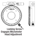
The rotation dial face features a laser-engraved scale marked at 1° increments and can be rotated manually using the knurled outer surface (see Figure G3.1). The thumbscrew, located on the lower right side of the mount, locks the dial face and engages the micrometer for fine adjustment. When locked, the micrometer provides ±7° of rotation at approximately 2.4 arcmin per micrometer division.
The PRM1(/M) is ideal for mounting either our SM1PM10 or SM1PM15 Polarizing Prism Mounts, both of which feature compatible SM1 threading. It can be purchased bundled with our SM1PM10 (Item# PRM1GL10(/M) below). Together they provide 360° of high precision rotation for either our 10 mm Glan-Laser or Glan-Taylor Polarizer (sold separately).
The PRM1(/M) is also compatible with our 30 mm cage system. The cage system can be mounted to the unit using ER cage assembly rods attached to the four 4-40 tapped holes located on the rotation dial face (there are no 4-40 tapped holes on the back of the mount). When using this product the entire 30 mm cage system will be rotated, not just the optic. Pairing this with our CPU1 Rotating Cage Plate will allow for a rotating cage segment between the PRM1 and a fixed cage system.

- PRM1(/M) Ø1" Rotation Mount Bundled with the SM1PM10 Prism Mount
- 360° Continuous Coarse Rotation
- Direct Read 1° Graduations on Main Dial
- ±7° of Micrometer-Driven Fine Rotation when Locked
- Vernier Scale with 5 arcmin Resolution
- Compatible with our 30 mm Cage System
- Bottom-Located 8-32 (M4) Tapped Hole for Post Mounting
The PRM1GL10(/M) bundles our PRM1(/M) rotation mount featured above with our SM1PM10 polarizing prism mount. The SM1PM10, which features external SM1 threading, is directly compatible with the PRM1(/M). Its rotating cover allows the user to block the two side ports when they are not required. The PRM1GL10(/M) provides 360° of high-precision coarse rotation for either our 10 mm Glan-Laser or Glan-Taylor Polarizer (sold separately).
The PRM1GL10(/M) is also compatible with our 30 mm cage system. The cage system can be mounted to the unit using ER cage assembly rods attached to the four 4-40 tapped holes on the rotation dial face (there are no 4-40 tapped holes on the back of the mount). When using this product, the entire 30 mm cage system will be rotated, not just the optic. Pairing this with our CPU1 Rotating Cage Plate will allow for a rotating cage segment between the PRM1 and a fixed cage system.

Click for Details
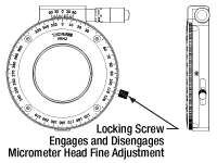
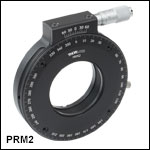
Figure 436A PRM2(/M) Mechanical Drawings
- Accepts Ø2" (Ø50.8 mm) Optics Up to 0.48" (12.2 mm) Thick
- 360° Continuous Coarse Rotation
- Direct Read 1° Graduations Engraved on Rotation Dial Face
- ±7° of Micrometer-Driven Fine Rotation when Locked
- Vernier Scale with 5 arcmin Resolution
- Compatible with our SM2 Lens Tubes and 60 mm Cage System
- One SM2RR Retaining Ring Included
- Bottom-Located 8-32 (M4) Tapped Hole for Post Mounting
The PRM2(/M) high-precision rotation mount for Ø2" optics combines 360° of continuous coarse manual rotation with precise, backlash-free micrometer adjustment. The SM2-threaded (2.035"-40) inner bore accepts Ø2" optics up to 0.48" (12.2 mm) thick as well as any of our SM2-threaded components. Optics are secured with one SM2RR retaining ring (included with each mount).
The rotation dial face features a laser-engraved scale marked at 1° increments and can be rotated manually using the knurled outer surface (see Figure 436A). The thumbscrew, located on the lower right side of the mount, locks the dial face and engages the micrometer for fine adjustment. When locked, the micrometer provides ±7° of rotation at approximately 1.7 arcmin per micrometer division. This rotation mount also features a 0.05" hex setscrew on both sides that can lock both the fine and coarse rotational movement. If replacement setscrews are needed, we offer SS4B025 brass setscrews, which use a 0.05" (1.3 mm) hex.
The PRM2(/M) is also compatible with our 60 mm cage system. The cage system can be mounted to the unit using ER cage assembly rods attached to the four 4-40 tapped holes located on the rotation dial face or the four 4-40 tapped holes located on the back side of the mount. The cage system attached to the back of the mount does not rotate.
 Products Home


 Zoom
Zoom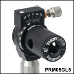
 Precision Rotation Mounts