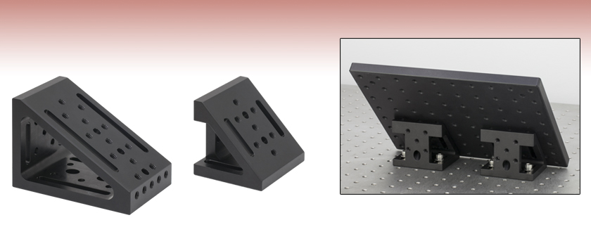
30°/60° and 45° Angled Mounting Plates

- Mount Optomechanics or Breadboards at 30°, 45°, or 60°
- 1/4" (M6) Slotted, 1/4" (M6) Counterbored, and 1/4"-20 (M6)
Tapped Holes Provide Flexible Mounting Options
AP30
30°/60° Mounting Plate
AP45
45° Mounting Plate
Breadboard Mounted at 45° Using Two AP45 Mounting Plates

Please Wait
This Animation Shows the Locations of the Tapped Holes, Counterbored Slots, and Counterbores on the AP30(/M)
Features
- One-Piece Aluminum Construction for Excellent Rigidity
- Triangular Cross-Section Design for Strong and Stable Mounting
- ±30 arcmin Angular Tolerance
- 0.001" (0.025 mm) Flatness
The AP30(/M) and AP45(/M) Angled Mounting Plates are ideal solutions for building sturdy three-dimensional optomechanical assemblies. They have a one-piece construction with an angular tolerance of ±30 arcmin for precise mounting of optical breadboards and components.
The AP30(/M) angled mounting plate provides a 4.48" x 2.88" (113.9 mm x 73.2 mm) mounting surface at a 30° or 60° angle. The mounting surface has two 3" long 1/4" (M6) counterbored slots, three 1/4" (M6) counterbores (facing out), and twelve 1/4"-20 (M6) tapped holes for a variety of mounting options. The surface opposite the 60° angle has two 2" long 1/4" (M6) counterbored slots, eight 1/4"-20 (M6) tapped holes, and three access holes for the counterbores on the mounting surface. The surface opposite the 30° angle has two 1" long 1/4" (M6) counterbored slots and seven 1/4"-20 (M6) tapped holes. A small flat surface at the 30° angle has an additional five 1/4"-20 (M6) tapped holes.
The AP45(/M) angled mounting plate has a 2.10" x 2.88" (78.8 mm x 73.2 mm) mounting surface with two 1" long 1/4" (M6) counterbored slots, two 1/4" (M6) counterbores (facing out), and seven 1/4"-20 (M6) tapped holes. The base has two 1" long 1/4" (M6) counterbored slots and an access hole for one counterbore on the mounting surface, while the back surface (visible in the application image above) has five 1/4"-20 (M6) tapped holes and another counterbore access hole.
Thorlabs also offers 90° mounting plates and adjustable mounting plates.
| Posted Comments: | |
s.m.walker
(posted 2018-04-11 16:18:19.497) For the AP45/M is there any reason why the slots on the hypotenuse can't be extended so that they are >50mm long? This would allow a component with 50mm spaced holes to be mounted in the center. llamb
(posted 2018-04-13 08:27:22.0) Hello, thank you for your feedback. Currently the AP45(/M) does not have the clearance space on the interior of its hypotenuse to allow >50 mm long slots to go all the way through. I will add this suggestion to our internal product forum and reach out to you directly for a possible customized solution. walter
(posted 2018-03-23 15:31:11.153) For the AP30/M on the diagonal side (surface A in drawing) a fifth pair of M6x1.0 Mounting Holes would be practical. With these holes it would be possible to fix a XT95P3 mount for connecting an XT95 profile.
I have a setup with an XT95 profile standing vertical on a breadboard and I want to mount another XT95 at an angle of 30° to this profile to make the setup more stable. llamb
(posted 2018-03-31 10:30:49.0) Hello, thank you for your feedback. I will add this idea to our internal product forum and reach out to you directly to discuss a possible customization in the meantime. valerios
(posted 2014-03-03 00:39:54.72) What is the maximum weight that can be loaded on the AP45 when setting it to 45 degree?
If not would it be possible to have a larger version of the AP45 (~20 cm x 20 cm)? At which price?
Regards,
Valerio cdaly
(posted 2014-03-25 05:00:04.0) Response from Chris at Thorlabs: Thank you for your inquiry. I'm afraid we do not have a load spec for this bracket. I've run some simulations and should be able to take quite a bit, but these are not number we would feel comfortable posting as they are not proven. I will contact you directly to discuss the load which you would like to use. Hopefully we can give you a decisive answer on whether or not the bracket is appropriate for your needs. |
 Products Home


 30°/60° and 45° Angled Mounting Plates