Mounted LEDs

- UV, Visible, IR, and Mid-IR Models Available
- Optimized Heat Management Results in Stable Output
- Internal SM1 (1.035"-40) Threading
- Collimation Adapters Available Separately
M405LP1
405 nm,
1200 mW Minimum Output Power
M505L4
505 nm,
400 mW Minimum Output Power
Mounted LED used as a Light Source for a DIY Cerna® Microscope
OVERVIEW
| Webpage Features | |
|---|---|
| Clicking this icon opens a window that contains specifications, mechanical drawings, and information about driver and collimator compatibility. | |
| Clicking this icon allows you to download our standard support documentation. | |

Click to Enlarge
The MWWHL4 LED and COP1-A microscope collimation adapter used as a trans-illumination source for an Olympus microscope.

Click to Enlarge
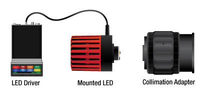
A mounted LED requires an LED driver to run; a collimation adapter (optional) collimates the diverging beam emitted by the LED. See the tables below to determine the appropriate LED driver. To determine the needed collimation adapter for a given LED, see the info icons (
Mounted LED Features
- Wavelengths Ranging from 265 nm to 5200 nm (See LED Quick Links Table to the Right)
- White, Broadband, and Dual-Peak LEDs Also Available
- Integrated Memory Stores LED Operating Parameters
- Thermal Properties Optimized for Stable Output Power
- Microscope- and SM-Thread-Compatible Collimation Adapters Available
- 4-Pin Female Mating Connector for Custom Power Supplies can be Purchased Separately
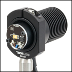
Each Thorlabs uncollimated, mounted LED consists of a single LED mounted to the end of a heat sink with 6 mm deep, SM1 (1.035"-40) internal threads. LEDs with Ø1.20" heat sinks have the same outer diameter as an SM1 Lens Tube, allowing them to fit inside a 30 mm Cage System. A selection of our LEDs are mounted to larger heat sinks, as they generate more heat during operation. These heat sinks are enclosed in Ø57.0 mm vented plastic housings and include four 4-40 tapped holes on the front for integration with 30 mm cage systems.
Every LED features an EEPROM chip which stores information about the LED (e.g., current limit, wavelength, forward voltage). When controlled by a Thorlabs LED driver designed to read the EEPROM chip, the data can be used to implement smart safety features.
These mounted LEDs possess good thermal stability properties, eliminating the issue of degradation of optical output power due to increased LED temperature. For more details, please see the Stability tab.
Please note that mounted LEDs are not intended for use in household illumination applications.
LED Collimation
Our adjustable collimation adapters can translate a Ø1" (Ø25 mm) or Ø2" (Ø50 mm) lens by up to 11 mm or 20 mm, respectively. Each adjustable collimation adapter includes an internal SM2 (2.035"-40) thread adapter so that the LEDs can be easily integrated with Thorlabs' SM2-threaded components, such as our Ø2" lens tubes. These adapters are offered in versions with and without an AR-coated aspheric condenser lens.
In addition, microscope collimation adapters are available that incorporate an AR-coated aspheric lens. These adapters mate to the epi-illumination ports on select Leica DMI, Nikon Eclipse Ti, Olympus IX/BX, or Zeiss Axioskop microscopes. Thorlabs also offers mounted LEDs with pre-attached microscope collimation adapters.
We offer suggestions for collimating most LEDs. Click on the info icon (![]() ) for each LED below for details. The Collimation tab provides additional information on collimating an LED.
) for each LED below for details. The Collimation tab provides additional information on collimating an LED.
Driver Options
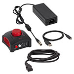
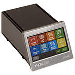
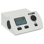
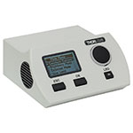
Thorlabs offers six drivers compatible with some or all of these LEDs: LEDD1B, UPLED, DC40, DC2200, DC4100, and DC4104 (the latter two require the DC4100-HUB). See the tables below for driver compatibility information, and the LED Drivers tab for a list of specifications. The UPLED, DC40, DC2200, DC4100, and DC4104 drivers are capable of reading the current limit from the EEPROM chip of the connected LED and automatically adjusting the maximum current setting to protect the LED.
Multi-LED Source
A customizable multi-LED source may be constructed using our mounted LEDs and other Thorlabs items. This source may be configured for integration with Thorlabs' versatile SM1 Lens Tube Systems and 30 mm Cage Systems. Please see the Multi-LED Source tab for a detailed item list and instructions.
Thorlabs also offers integrated, user-configurable 4-Wavelength High-Power LED Sources.
RELATIVE POWER
Relative Power
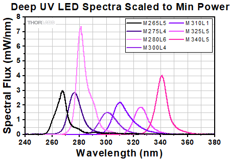
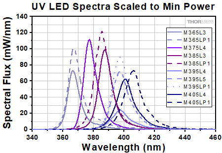
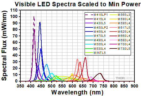
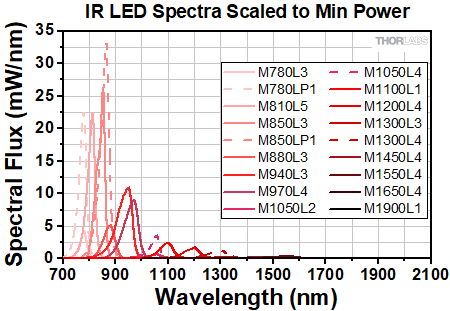
The actual spectral output and total output power of any given LED will vary due to variations in the manufacturing process and operating parameters, such as temperature and current. Both a typical and minimum output power are specified to help you select an LED that suits your needs. Each mounted LED will provide at least the minimum specified output power at the maximum current. In order to provide a point of comparison for the relative powers of LEDs with different nominal wavelengths, the spectra in the plots below have been scaled to the minimum output power for each LED. This data is representative, not absolute. Excel files with normalized and scaled spectra for each set of the mounted LEDs can be downloaded by clicking below the graphs.
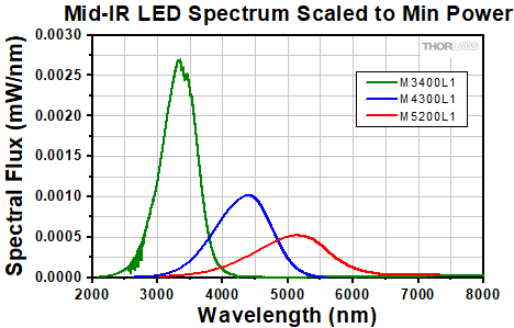
Click to Enlarge
Click Here for Data
The spectrum shown for M4300L1 and M5200L1 are ideal.
Please see their Spec Sheets for more information.
STABILITY

Click to Enlarge
Our 340 nm mounted LED has a typical lifetime of >3,000 hours. In this case, the unit under test continued to provide more than 90% of its initial power after 45 days.
LED Lifetime and Long-Term Power Stability
One characteristic of LEDs is that they naturally exhibit power degradation with time. Often this power degradation is slow, but there are also instances where large, rapid drops in power, or even complete LED failure, occur. LED lifetimes are defined as the time it takes a specified percentage of a type of LED to fall below some power level. The parameters for the lifetime measurement can be written using the notation BXX/LYY, where XX is the percentage of that type of LED that will provide less than YY percent of the specified output power after the lifetime has elapsed. Thorlabs defines the lifetime of our LEDs as B50/L50, meaning that 50% of the LEDs with a given item # will fall below 50% of the initial optical power at the end of the specified lifetime. For example, if a batch of 100 LEDs is rated for 150 mW of output power, 50 of these LEDs can be expected to produce an output power of ≤75 mW after the specified LED lifetime has elapsed.
The sample plot to the right shows example data from long-term stability testing over a 45 day period for a 340 nm mounted LED, which had a lifetime of >3,000 hours (~125 days). The small power drop experienced by the LED after it is turned on is typical behavior during the first few minutes of operation. It corresponds to the period of time required for the LED to warm up to the point where it is thermally stable. Please note that this graph represents the performance of a single LED; the performance of individual LEDs will vary within the stated specifications.
Optimized Thermal Management
The thermal dissipation performance of these mounted LEDs has been optimized for stable power output. The heat sink is directly mounted to the LED mount so as to provide optimal thermal contact. By doing so, the degradation of optical output power that can be attributed to increased LED junction temperature is minimized (see the graph to the left).
COLLIMATION
Video Insight: Collimate Light from an LED
Collimating light from an LED or other large, incoherent source can be a surprisingly challenging task. The emitter’s size and the collimating lens’ focal length and numerical aperture (NA) all influence the characteristics of the collimated beam. It can also be hard to know when the lens is positioned optimally. In this video, two collimation approaches are demonstrated. In addition, two lenses with different NAs and focal lengths are used to show that a benefit of increasing the lens’ NA is collecting more power from the LED, but that a higher NA comes at a cost of increasing the rate at which the collimated beam diverges.
Two Collimation Methods for LEDs
As demonstraded in the Video Insight above, the distance between the selected collimating optic and the LED may need to be adjusted to ensure that the LED is suitably collimated. Collimation can only be achieved over a local region of the beam path. In this collimated region the beam has minimal divergence and will not converge at any point (see images below for comparison). As with any beam, perfect collimation is not achievable; any collimated beam diverges at some rate. For incoherent sources like LEDs, the rate of divergence is higher when the emitter size is larger. Two methods for achieving a collimated beam are outlined here.
Method 1: Form an Image of the LED at Infinity
- Power on the LED.
- Place a viewing screen ~1-2 feet away from the collimating optic.
- Adjust the distance between the collimating optic and the LED to form an image of the LED on the viewing screen (Image A below).
- Move the viewing screen farther away from the LED.
- Repeat steps 3 and 4 as much as space allows.
- Returning the viewing screen to ~1-2 feet away from the collimating optic should show a non-converging, homogenous beam. The beam should be somewhat circular, may have a slightly polygonal shape, and should not be a clear image of the LED itself. Image C shows an example of a collimated beam.
- Once the optimal position of the collimating optic has been found, lock the position of the collimating optic in place.
Note: Space contraints may limit this approach's usefulness. When space is limited, method 2 (below) may be more advantageous.

Click to Enlarge
Image A: Image of the LED
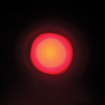
Click to Enlarge
Image B: Uncollimated Beam

Click to Enlarge
Image C: Collimated Beam
Method 2: Use the Divergence of the Beam to Set the Collimating Optic Position
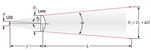
- Determine the expected beam diameter (D2) a distance L away from the output of the collimating optic:
Click to Enlarge
Figure 1: Expected beam divergence after the collimating optic. Light emitted by an LED of size d is collected by a lens of diameter D1 and focal length f, which yields a divergence angle Φ after the lens. A distance L away from the lens the beam has expanded to size D2 = D1 + ΔD.
Figure 1 shows the propagation of the beam emitted by the LED and passing through the collimating optic. The expected divergence angle of the beam (Φe) after the collimating optic is given by


- Power on the LED.
- Place a viewing screen at distance L away, and adjust the position of the collimating optic to set D2 on the viewing screen.
- This is the optimal position of the collimating optic; lock the position of the collimating optic in place.
The table below provides examples of how the half viewing angle changes for select LEDs with the addition of a Ø1" aspheric condenser lens (ACL2520U). See the Collimation Adapter tab in the info icons ( ![]() ) below for the recommended collimating optic for select LEDs.
) below for the recommended collimating optic for select LEDs.
| Item # | Color | Nominal Wavelengtha |
Calculated Lens to Emitter Distanceb | Half Viewing Anglec | ||
|---|---|---|---|---|---|---|
| +1 mm Out of Focusd | at Calculated Focusing Distance | -1 mm Out of Focusd | ||||
| M850L3 | IR | 850 nm | 13.8 mm | 3.29° | 3.10° | 3.93° |
| M940L3 | IR | 940 nm | 13.9 mm | 3.42° | 2.46° | 3.70° |
PIN DIAGRAM

| Pin | Specification | Color |
|---|---|---|
| 1 | LED Anode | Brown |
| 2 | LED Cathode | White |
| 3 | EEPROM GND | Black |
| 4 | EEPROM IO | Blue |
Pin Connection - Male
The diagram to the right shows the male connector of the mounted LED assembly. It is a standard M8 x 1 sensor circular connector. Pins 1 and 2 are the connection to the LED. Pin 3 and 4 are used for the internal EEPROM in these LEDs. If using an LED driver that was not purchased from Thorlabs, be careful that the appropriate connections are made to Pin 1 and Pin 2 and that you do not attempt to drive the LED through the EEPROM pins.
MULTI-LED SOURCE

Click to Enlarge
Multi-LED Source Coupled to Microscope Illumination Port
Creating a Custom Multi-LED Source for Microscope Illumination
Thorlabs offers the items necessary to create your own custom multi-LED light source using two or three of the mounted LEDs offered below. As configured in the following example, the light source is intended to be used with the illumination port of a microscope. However, it may be integrated with other applications using Thorlabs' versatile SM1 Lens Tube and 30 mm Cage Systems. Thorlabs also offers integrated, user-configurable 4-Wavelength LED Sources.
Design & Construction
First, light will be collimated by lenses mounted in lens tubes. Dichroic mirrors mounted in kinematic cage cubes then combine the output from the multiple LEDs. The mounted LEDs may be driven by LEDD1B Compact T-Cube LED Drivers (power supplies are sold separately). The LEDD1B LED Drivers allow each LED's output to be independently modulated and can provide up to 1200 mA of current. Please take care not to drive the LED sources above their max current ratings.
When designing your custom source, select mounted LEDs from below along with dichroic mirror(s) that have cutoff wavelength(s) between the LED wavelengths. The appropriate dichroic mirror(s) will reflect light from side-mounted LEDs and transmit light along the optical axis. Please note that most of these dichroic mirrors are "longpass" filters, meaning they transmit the longer wavelengths and reflect the shorter wavelengths. To superimpose light from three or more LEDs, add each in series (as shown below), starting from the back with longer wavelength LEDs when using longpass filters. Shortpass filters may also used if the longer wavelength is reflected and the shorter wavelength is transmitted. Sample combinations of compatible dichroic mirrors and LEDs are offered in the three tables below.
It is also necessary to select an aspheric condenser lens for each source with AR coatings appropriate for the source. Before assembling the light source, collimate the light from each mounted LED as detailed in the Collimation tab. For mounting the aspheric lenses in the SM1V05 Lens Tubes using the included SM1RR retaining rings, we recommend the SPW801 Adjustable Spanner Wrench. A properly collimated LED source should have a resultant beam that is approximately homogenous and not highly divergent at a distance of approximately 2 feet (60 cm). An example of a well-collimated beam is shown on the Collimation tab.
After each LED source is collimated, thread the SM1V05 Lens Tubes at the end of each collimated LED assembly into their respective C4W Cage Cube ports using SM1T2 Lens Tube Couplers. Install each dichroic filter in an FFM1 Dichroic Filter Holder, and mount each filter holder onto a B4C Kinematic Cage Cube Platform. Each platform is then installed in the C4W Cage Cubes by partially threading the included screws into the bottom of the cube, and then inserting and rotating the B4C platform into place. Align the platform to the desired position and then firmly tighten the screws. To connect multiple cage cubes and the microscope adapter, use the remaining SM1T2 lens tube couplers along with an SM1L05 0.5" Lens Tube between adjacent cage cubes. Finally, adjust the rotation, tip, and tilt of each B4C platform to align the reflected and transmitted beams so they overlap as closely as possible.
If desired, a multi-LED source may be constructed that employs more than three LEDs. The limiting factors for the number of LEDs that can be practically used are the collimation of the light and the dichroic mirror efficiency over the specified range. Heavier multi-LED sources may be supported with our Ø1" or Ø1.5" Posts.

Click to Enlarge
Three-LED Source Using Components Mounted LEDs and Dichroic Mirrors
Detailed in Example Configuration 1
| Parts List | |||||
|---|---|---|---|---|---|
| # | Product Description | Item # | 2 LEDs | 3 LEDs | |
| Item Qty. | |||||
| 1 | Microscope Illumination Port Adapter: |
Olympus IX or BX | SM1A14 | 1 | 1 |
| Leica DMI | SM1A21 | ||||
| Zeiss Axioskop | SM1A23a | ||||
| Nikon Eclipse Ti | SM1A26 | ||||
| 2 | Mounted LEDb | - | 2 | 3 | |
| - | T-Cube LED Driver, 1200 mA Max Drive Current | LEDD1Bc | 2 | 3 | |
| - | 15 V Power Supply for K- and T-Cube | KPS201c | 2 | 3 | |
| 3 | 4-Way Mounting 30 mm Cage Cube | C4W | 1 | 2 | |
| 4 | Kinematic Cage Cube Platform for C4W/C6W | B4C | 1 | 2 | |
| 5 | 30 mm Cage-Compatible Dichroic Filter Mount | FFM1 | 1 | 2 | |
| 6 | Dichroic Filter(s)d | - | 1 | 2 | |
| 7 | Externally SM1-Threaded End Cap | SM1CP2 | 1 | 2 | |
| 8 | SM1 (1.035"-40) Coupler, External Threads, 0.5" Long | SM1T2 | 3 | 5 | |
| 9 | Ø1" SM1 Lens Tube, 1/2" Long External Threads | SM1V05 | 2 | 3 | |
| - | Aspheric Condenser Lens |
AR-Coated 350 - 700 nm | ACL2520U-Ac,e | 2 | 3 |
| AR-Coated 650 - 1050 nm | ACL2520U-Bc,e | ||||
| 10 | SM1 Lens Tube, 0.3" Thread Depth | SM1L03 | 2 | 4 | |
| - | Blank Cover Plate with Rubber O-Ring for C4W/C6W | B1Cc | 1 | 2 | |

Click to Enlarge
Beam Profile of Source with 3 Mounted LEDs
Click to Enlarge
Two-LED source. This is the same as Example 1, but with the blue LED removed.
RAY DATA
Ray data for Zemax is available for some of the bare LEDs incorporated into these high-powered light sources. This data is provided in a zipped folder that can be downloaded by clicking on the red document icons (![]() ) next to the part numbers in the pricing tables below. Every zipped folder contains an information file and one or more ray files for use with Zemax:
) next to the part numbers in the pricing tables below. Every zipped folder contains an information file and one or more ray files for use with Zemax:
- Information File: This document contains a summary of the types of data files included in the zipped folder and some basic information about their use. It includes a table listing each document type and the corresponding filenames.
- Ray Files: These are binary files containing ray data for use with Zemax.
For the LEDs marked with an superscript "a" in the table to the right, the following additional pieces of information are also included in the zipped folder:
- Radiometric Color Spectrum: This .spc file is also intended for use with Zemax.
- CAD Files: A file indicating the geometry of the bare LED. For the dimensions of the high-power mounted LEDs that include the package, please see the support drawings provided by Thorlabs.
- Sample Zemax File: A sample file containing the recommended settings and placement of the ray files and bare LED CAD model when used with Zemax.
The table to the right summarizes the ray files available for each LED and any other supporting documentation provided.
USE WITH CERNA
| Components for Cerna® Compatibility |
|---|
| Epi-Illumination |
| WFA2001 Epi-Illuminator Module |
| Trans-Illumination |
| Illumination Kits |
Using Mounted LEDs in Cerna® Microscope Systems
Mounted LEDs, which can have either narrowband or broadband spectra, are useful for a range of applications within Thorlabs' Cerna microscopy platform:
- Fluorescence Microscopy
- Brightfield Microscopy
- Near Infrared/Infrared (NIR/IR) Microscopy
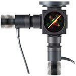
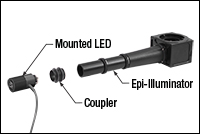
If you are interested in using a mounted LED with a Cerna modular microscopy system, the mounted LED can be attached by way of the single-cube epi-illuminator module (Item # WFA2001), which contains AR-coated optics optimized for the 350 - 700 nm wavelength range. The mounted LED and epi-illuminator module are connected together by an externally threaded coupler (Item # SM1T10, provided with the WFA2001), which includes two knurled locking rings (Item # SM1NT, also provided with the WFA2001) that are tightened by hand. The mounted LED is then powered by a driver, sold separately. Please see the LED Drivers tab to identify the appropriate driver for your mounted LED. If you wish to connect multiple mounted LEDs to the epi-illuminator module, contact Technical Support.
 Click to Enlarge
An exploded view of the mounted LED and its connection with the WFA2001 epi-illuminator module.
 Click to Enlarge
Attaching the mounted LED is possible before or after connecting the epi-illuminator module to the microscope.
 Click to Enlarge
The mounted LED and epi-illuminator module attached to the Cerna microscope.
Please see the Overview tab to choose the appropriate color spectrum of mounted LED for your imaging needs. Again, note that the epi-illuminator module is optimized for 350 - 700 nm wavelength illumination sources.
Certain mounted LEDs are also compatible with our illumination kits for trans-illumination. Please contact Technical Support if you wish to use an LED not currently offered as a component of these kits, as the collimating optics are optimized for certain beam characteristics.
LED DRIVERS
To fully support the max optical power of the LED you intend to drive, ensure that the max voltage and max current of the driver are equal to or greater than those of the LED. Drivers matching these conditions are listed in the Recommended Drivers columns of the LED tables below.
| Compatible Drivers | LEDD1B | UPLEDa | DC40a | DC2200a | DC4100a,b | DC4104a,b |
|---|---|---|---|---|---|---|
| Click Photos to Enlarge | 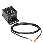 |
 |
 |
 |
 |
 |
| LED Driver Current Output (Max)c | 1.2 A | 1.2 A | 4.0 Ad | LED1 Terminal: 10.0 A LED2 Terminal: 2.0 Ae |
1.0 A per Channel | 1.0 A per Channel |
| LED Driver Forward Voltage (Max)f | 12 V | 8 V | 14.0 Vd | 50 V | 5 V | 5 V |
| Modulation Frequency Using External Input (Max) | 5 kHzg | - | 5 kHzg | 250 kHzg,h | 100 kHzg (Simultaneous Across all Channels) |
100 kHzg (Independently Controlled Channels) |
| External Control Interface(s) | Analog (BNC) | USB 2.0 | USB 2.0, TTL, and Analog (BNC) | USB 2.0 and Analog (BNC) | USB 2.0 and Analog (BNC) | USB 2.0 and Analog (8-Pin) |
| Main Driver Features | Very Compact Footprint 60 mm x 73 mm x 104 mm (W x H x D) |
USB-Controlled | Driver Current Up to 4.0 A, Manual and USB-Controlled |
Touchscreen Interface with Internal and External Options for Pulsed and Modulated LED Operation | 4 Channelsb | 4 Channelsb |
| EEPROM Compatible: Reads Out LED Data for LED Settings | - | |||||
| LCD Display | - | - | - |
LED SELECTION GUIDE
This tab includes all LEDs sold by Thorlabs. Click on More [+] to view all available wavelengths for each type of LED pictured below.
| Light Emitting Diode (LED) Selection Guide | ||||||
|---|---|---|---|---|---|---|
| Click Photo to Enlarge (Representative; Not to Scale) |
 |
 |
 |
 |
 |
 |
| Type | Unmounted LEDs | Pigtailed LEDs | LEDs in SMT Packages |
LED Arrays | LED Ring Light | Cage-Compatible Diffuse Backlight LED |
| Light Emitting Diode (LED) Selection Guide | ||||||
|---|---|---|---|---|---|---|
| Click Photo to Enlarge (Representative; Not to Scale) |
 |
 |
 |
 |
 |
 |
| Type | PCB- Mounted LEDs |
Heatsink- Mounted LEDs |
Collimated LEDs for Microscopyb | Fiber- Coupled LEDsc |
High-Power LEDs for Microscopy | Multi-Wavelength LED Source Optionsd |
Deep UV Mounted LEDs (265 - 340 nm)

Please note that our deep UV LEDs radiate intense UV light during operation. Precautions must be taken to prevent looking directly at the UV light, and UV light protective glasses must be worn to avoid eye damage. Exposure of the skin and other body parts to UV light should be avoided.
Part Number | Description | Price | Availability |
|---|---|---|---|
M265L5 | 265 nm, 38.4 mW (Min) Mounted LED, 440 mA | $482.24 | 3-5 Days |
M275L4 | 275 nm, 45 mW (Min) Mounted LED, 700 mA | $407.62 | 3-5 Days |
M280L6 | 280 nm, 78 mW (Min) Mounted LED, 500 mA | $432.64 | 3-5 Days |
M300L4 | 300 nm, 26 mW (Min) Mounted LED, 350 mA | $546.44 | 3-5 Days |
M310L1 | 308 nm, 38.5 mW (Min), Mounted LED, 600 mA | $617.06 | Lead Time |
M325L5 | 325 nm, 25 mW (Min) Mounted LED, 600 mA | $713.55 | 3-5 Days |
M340L5 | 340 nm, 45.5 mW (Min) Mounted LED, 600 mA | $429.80 | 3-5 Days |
UV Mounted LEDs (365 - 405 nm)

Please note that our UV LEDs radiate intense UV light during operation. Precautions must be taken to prevent looking directly at the UV light, and UV light protective glasses must be worn to avoid eye damage. Exposure of the skin and other body parts to the UV light should be avoided.
Part Number | Description | Price | Availability |
|---|---|---|---|
M365L3 | 365 nm, 880 mW (Min) Mounted LED, 1000 mA | $417.16 | 3-5 Days |
M365LP1 | 365 nm, 1350 mW (Min) Mounted LED, 1700 mA | $506.06 | 3 Weeks |
M375L4 | 375 nm, 1270 mW (Min) Mounted LED, 1400 mA | $197.98 | 3 Weeks |
M385L3 | 385 nm, 1240 mW (Min) Mounted LED, 1000 mA | $417.16 | 3 Weeks |
M385LP1 | 385 nm, 1650 mW (Min) Mounted LED, 1700 mA | $506.06 | 3-5 Days |
M395L4 | 395 nm, 400 mW (Min) Mounted LED, 500 mA | $307.38 | 3 Weeks |
M395L5 | 395 nm, 1130 mW (Min) Mounted LED, 1000 mA | $417.16 | 3-5 Days |
M395LP1 | 395 nm, 1420 mW (Min) Mounted LED, 1400 mA | $506.06 | 3-5 Days |
M405L4 | 405 nm, 1000 mW (Min) Mounted LED, 1000 mA | $256.22 | 3-5 Days |
M405LP1 | 405 nm, 1200 mW (Min) Mounted LED, 1400 mA | $506.06 | 3-5 Days |
Single-Color Cold Visible Mounted LEDs (415 - 565 nm)

Please note that the 415 nm (violet), 430 nm (violet), and 450 nm (royal blue) LEDs radiate intense UV light during operation. Precautions must be taken to prevent looking directly at the UV light, and UV light protective glasses must be worn to avoid eye damage. Exposure of the skin and other body parts to the UV light should be avoided.
Part Number | Description | Price | Availability |
|---|---|---|---|
M415L4 | 415 nm, 1310 mW (Min) Mounted LED, 1500 mA | $232.92 | 3-5 Days |
M415LP1 | 415 nm, 1640 mW (Min) Mounted LED, 2000 mA | $349.39 | 3 Weeks |
M430L5 | 430 nm, 529.2 mW (Min) Mounted LED, 500 mA | $216.32 | 3-5 Days |
M450LP2 | 450 nm, 2118.1 mW (Min) Mounted LED, 2000 mA | $266.10 | 3 Weeks |
M455L4 | 455 nm, 1150 mW (Min) Mounted LED, 1000 mA | $242.93 | 3 Weeks |
M470L5 | 470 nm, 809 mW (Min) Mounted LED, 1000 mA | $244.11 | 3-5 Days |
M490L4 | 490 nm, 205 mW (Min) Mounted LED, 350 mA | $226.89 | 3-5 Days |
M505L4 | 505 nm, 520 mW (Typ.) Mounted LED, 1000 mA | $325.49 | 3-5 Days |
M530L4 | 530 nm, 370 mW (Min) Mounted LED, 1000 mA | $325.49 | 3-5 Days |
MINTL5 | 554 nm, 650 mW (Min) Mounted LED, 1225 mA | $310.95 | 3-5 Days |
M565L3 | 565 nm, 880 mW (Min) Mounted LED, 1000 mA | $256.59 | 3 Weeks |
Single-Color Warm Visible Mounted LEDs (590 - 730 nm)

Part Number | Description | Price | Availability |
|---|---|---|---|
M590L4 | 590 nm, 230 mW (Min) Mounted LED, 1000 mA | $237.46 | 3-5 Days |
M595L4 | 595 nm, 820 mW (Min) Mounted LED, 1500 mA | $274.44 | 3-5 Days |
M617L5 | 617 nm, 737.4 mW (Min) Mounted LED, 1000 mA | $243.10 | 3-5 Days |
M625L4 | 625 nm, 700 mW (Min) Mounted LED, 1000 mA | $237.46 | Lead Time |
M660L4 | 660 nm, 940 mW (Min) Mounted LED, 1200 mA | $256.59 | 3-5 Days |
M680L4 | Customer Inspired! 680 nm, 180 mW (Min) Mounted LED, 600 mA | $230.46 | Lead Time |
M700L4 | 700 nm, 80 mW (Min) Mounted LED, 500 mA | $230.46 | 3-5 Days |
M730L5 | 730 nm, 540 mW (Min) Mounted LED, 1000 mA | $243.11 | 3-5 Days |
IR Mounted LEDs (780 - 1900 nm)

Part Number | Description | Price | Availability |
|---|---|---|---|
M780L3 | 780 nm, 200 mW (Min) Mounted LED, 800 mA | $256.59 | 3 Weeks |
M780LP1 | 780 nm, 800 mW (Min) Mounted LED, 800 mA | $388.47 | 3-5 Days |
M810L5 | 810 nm, 810 mW (Min) Mounted LED, 1000 mA | $284.25 | 3-5 Days |
M850L3 | 850 nm, 900 mW (Min) Mounted LED, 1200 mA | $256.59 | 3-5 Days |
M850LP1 | 850 nm, 1400 mW (Min) Mounted LED, 1500 mA | $406.28 | 3 Weeks |
M880L3 | 880 nm, 300 mW (Min) Mounted LED, 1000 mA | $256.59 | 3-5 Days |
M940L3 | 940 nm, 800 mW (Min) Mounted LED, 1000 mA | $256.59 | 3 Weeks |
M970L4 | 970 nm, 600 mW (Min) Mounted LED, 1000 mA | $197.98 | 3-5 Days |
M1050L2 | Customer Inspired! 1050 nm, 50 mW (Min) Mounted LED, 700 mA | $275.60 | 3-5 Days |
M1050L4 | 1050 nm, 160 mW (Min) Mounted LED, 600 mA | $335.42 | 3-5 Days |
M1100L1 | 1100 nm, 168 mW (Min) Mounted LED, 1000 mA | $353.98 | 3-5 Days |
M1200L4 | 1200 nm, 136 mW (Min) Mounted LED, 1000 mA | $338.57 | 3 Weeks |
M1300L3 | Customer Inspired! 1300 nm, 25 mW (Min) Mounted LED, 500 mA | $256.08 | 3-5 Days |
M1300L4 | 1300 nm, 122.8 mW (Min) Mounted LED, 1000 mA | $342.53 | 3-5 Days |
M1450L4 | 1450 nm, 81.8 mW (Min) Mounted LED, 1000 mA | $336.60 | 3 Weeks |
M1550L4 | 1550 nm, 46 mW (Min) Mounted LED, 1000 mA | $349.12 | 3 Weeks |
M1650L4 | 1650 nm, 13 mW (Min) Mounted LED, 600 mA | $341.23 | 3-5 Days |
M1900L1 | 1900 nm, 10 mW (Min) Mounted LED, 1000 mA | $383.96 | Lead Time |
Mid-IR Mounted LEDs (3400 - 5200 nm)
Part Number | Description | Price | Availability |
|---|---|---|---|
M3400L1 | 3400 nm, 2.2 mW (Min) Mounted LED, 200 mA | $1,302.63 | 3-5 Days |
M4300L1 | 4300 nm, 1.1 mW (Min) Mounted LED, 200 mA | $1,302.63 | 3 Weeks |
M5200L1 | 5200 nm, 0.8 mW (Min) Mounted LED, 200 mA | $1,277.09 | 3 Weeks |
Purple Mounted LED (455 nm / 640 nm)

Our dual-peak LED was designed for applications requiring illumination in both red and blue portions of the spectrum, such as horticulture. This purple LED features dual peaks at 455 nm and 640 nm, respectively, to stimulate photosynthesis (see graph to compare the absorption peaks of photosynthesis pigments with the LED spectrum). The LED was designed to maintain the red/blue ratio of the emission spectrum over its lifetime to provide high uniformity of plant growth.
Part Number | Description | Price | Availability |
|---|---|---|---|
MPRP1L4 | 455 nm (12.5%) / 640 nm, 275 mW (Min) Mounted LED, 300 mA | $174.71 | 3 Weeks |
White Mounted LEDs (400 - 700 nm Wavelength Range)

Our warm, neutral, and cold white LEDs feature broad spectra that span several hundred nanometers. The difference in appearance among these LEDs can be described using the correlated color temperature, which indicates that the LEDs color appearance is similar to a black body radiator at that temperature. In general, warm white LEDs offer a spectrum similar to a tungsten source, while cold white LEDs have a stronger blue component to the spectrum; neutral white LEDs provide a more even illumination spectrum over the visible range than warm white or cold white LEDs. Cold white LEDs are more suited for fluorescence microscopy applications or cameras with white balancing, because of a higher intensity at most wavelengths compared to warm white LEDs. Neutral white LEDs are ideal for horticultural applications.
Part Number | Description | Price | Availability |
|---|---|---|---|
MWWHL4 | 3000 K, 570 mW (Min) Mounted LED, 1000 mA | $200.76 | 3-5 Days |
MWWHLP2 | 3000 K, 1713 mW (Min) Mounted LED, 700 mA | $286.61 | 3-5 Days |
MWUVL1 | 4000 K, 235 mW (Min) Mounted LED, 125 mA | $178.60 | Lead Time |
MNWHLP1 | 4000 K, 1400 mW (Min) Mounted LED, 2000 mA | $347.88 | 3-5 Days |
MNWHL4 | 4900 K, 740 mW (Min) Mounted LED, 1225 mA | $174.71 | 3-5 Days |
MCWHL7 | 6500 K, 930 mW (Min) Mounted LED, 1300 mA | $236.10 | 3-5 Days |
MCWHLP2 | 6500 K, 942 mW (Min), Mounted LED, 1300 mA | $313.35 | 3-5 Days |
MCWHL8 | 6500 K, 1300.9 mW (Min), Mounted LED, 1400 mA | $254.24 | 3-5 Days |
MCWHLP3 | 6500 K, 2064.8 mW (Min), Mounted LED, 700 mA | $371.15 | Lead Time |
Broadband Mounted LEDs

The MBB1L3 broadband LED has a relatively flat spectral emission over a wide wavelength range. Its 10 dB bandwidth ranges between 470 nm and 850 nm. The MBB2L1 and MBB2LP1 broadband LEDs feature a spectrum with peaks at approximately 770 nm, 860 nm, and 940 nm.
Part Number | Description | Price | Availability |
|---|---|---|---|
MBB1L3 | 470 - 850 nm Mounted Broadband LED, 70 mW (Min), 500 mA | $598.71 | 3 Weeks |
MBB2L1 | IR Mounted Broadband LED (770 nm, 860 nm & 940 nm), 650 mW (Min), 800 mA | $627.09 | 3 Weeks |
MBB2LP1 | IR Mounted Broadband LED (770 nm, 860 nm & 940 nm), 740 mW (Min), 1000 mA | $733.07 | 3 Weeks |
Adjustable Collimation Adapters for Ø1" (Ø25 mm) or Ø2" (Ø50 mm) Optics

| LED Quick Links |
|---|
| Mounted LEDs |
| Deep UV (265 - 340 nm) |
| UV (365 - 405 nm) |
| Cold Visible (415 - 565 nm) |
| Warm Visible (590 - 730 nm) |
| IR (780 - 1900 nm) |
| Mid-IR (3400 - 5200 nm) |
| Purple (455 nm / 640 nm) |
| White (400 - 700 nm) |
| Broadband Mounted LEDs |
| LED Collimationa |
| Adjustable Collimation Adapters |
| Microscope Collimation Adapters |
| LED Mating Connector |
| LED Drivers |

Click to Enlarge
SM2F Adapter Installed on a M365LP1 Mounted LED
- Integrate a Ø1" (Ø25 mm) or Ø2" (Ø50 mm) Collimation Optic with Thorlabs' Mounted LEDs
- Adjust and Set Lens Position via Rotating Ring with Locking Setscrew
- Available with or without AR-Coated Lens (See Table Below for Details)
- Compatible with Thorlabs' SM2-Threaded Microscope Port Adapters
These adapters allow Ø1" (Ø25 mm) or Ø2" (Ø50 mm) collimation optics to be integrated with the mounted LEDs sold above. The adapters can translate a Ø1" or Ø2" lens by up to 11 mm or 20 mm, respectively. They are offered in versions without a collimation optic or with a removable AR-coated aspheric condenser lens for 350 - 700 nm or 650 - 1050 nm. All of these adapters attach to the LED housing via external SM1 threads, allowing them to be used with both the Ø30.5 mm and Ø57.0 mm housings.
The collimation lens is mounted in an inner carriage that provides non-telescoping, rotating translation along the Z-axis by turning the knurled adjustment ring (engraved with the item # in the photos to the left) and is locked into position by turning the locking screw on the side of the adjustment ring with a 2 mm (5/64") hex key. Lines, spaced 2 mm apart, are engraved on the housing as a rough guide for how far the carriage has been translated. These collimation adapters use an extra-thick SM1-threaded or SM2-threaded retaining ring designed for holding aspheric condenser lenses. The retaining rings can be tightened or loosened using either an SPW602 (Ø1" versions) or SPW604 (Ø2" versions) spanner wrench.
The threading on the input and output apertures remain fixed during translation, allowing these adapters to be mounted between fixed lens tubes. These apertures are threaded for compatibility with various components; please see the table below for details.
Inserting or Removing Optics
To insert or remove an optic in these collimation adapters, use the adjustment ring to translate the inner carriage to the output end of the housing. Remove the included retaining ring using the spanner wrench. If there is a lens installed already, remove it from the carriage. Insert another Ø1" (Ø25 mm) or Ø2" (Ø50 mm) optic into the carriage, and use the retaining ring to secure it.
Using a lens with a substrate or AR coating that does not transmit the wavelength of your LED is not recommended. Deep UV LEDs (wavelengths ≤ 340 nm) require a lens fabricated from UV Fused Silica, since many standard varieties of glass do not transmit below 350 nm. IR LEDs that emit at wavelengths ≥ 1050 nm can be collimated using an uncoated condenser lens, such as the Ø50 mm ACL50832U which has a wavelength range of 380 - 2100 nm.
| Item # | Compatible Optic |
Lens Travel Range |
Input Threading | Output Threading | Included Lens |
AR Coating Range |
Lens Focal Length |
Operating Temperature |
Diagram |
|---|---|---|---|---|---|---|---|---|---|
| SM1Ua | Ø1" (Ø25 mm) | 11 mm (0.43") | External SM1 (1.035"-40) | Internal SM2 (2.035"-40)b | N/A | N/A | N/A | 15 - 60 °C (Non-Condensing) |
|
| SM1U25-A | ACL2520U-A | 350 - 700 nm | 20.1 mm | ||||||
| SM1U25-B | ACL2520U-B | 650 - 1050 nm | 20.1 mm | ||||||
| SM2Fa | Ø2" (Ø50 mm) | 20 mm (0.79") | External SM1 (1.035"-40)c | Internal SM2 (2.035"-40)d | N/A | N/A | N/A | ||
| SM2F32-A | ACL50832U-A | 350 - 700 nm | 32.0 mm | ||||||
| SM2F32-B | ACL50832U-B | 650 - 1050 nm | 32.0 mm |
Part Number | Description | Price | Availability |
|---|---|---|---|
SM1U | Adjustable Collimation Adapter for Ø1" or Ø25 mm Optic | $297.50 | 3-5 Days |
SM1U25-A | Adjustable Collimation Adapter with Ø1" Lens, AR Coating: 350 - 700 nm | $316.16 | Lead Time |
SM1U25-B | Adjustable Collimation Adapter with Ø1" Lens, AR Coating: 650 - 1050 nm | $316.16 | 3-5 Days |
SM2F | Adjustable Collimation Adapter for Ø2" or Ø50 mm Optic | $294.61 | 3-5 Days |
SM2F32-A | Adjustable Collimation Adapter with Ø2" Lens, AR Coating: 350 - 700 nm | $313.61 | 3-5 Days |
SM2F32-B | Adjustable Collimation Adapter with Ø2" Lens, AR Coating: 650 - 1050 nm | $313.61 | 3-5 Days |
Microscope Collimation Adapters with Ø50 mm Lens
| LED Quick Links |
|---|
| Mounted LEDs |
| Deep UV (265 - 340 nm) |
| UV (365 - 405 nm) |
| Cold Visible (415 - 565 nm) |
| Warm Visible (590 - 730 nm) |
| IR (780 - 1900 nm) |
| Mid-IR (3400 - 5200 nm) |
| Purple (455 nm / 640 nm) |
| White (400 - 700 nm) |
| Broadband Mounted LEDs |
| LED Collimationa |
| Adjustable Collimation Adapters |
| Microscope Collimation Adapters |
| LED Mating Connector |
| LED Drivers |

Click for Details
Installation of a collimation adapter to a mounted LED using the SM2T2 and SM1A2 thread adapters. The same setup can be used to attach the collimation adapter to the LEDs above that use a Ø57.0 mm housing.
- AR-Coated Aspheric Lens with Low f/# (Approximately 0.8)
- Compatible with Select Leica, Nikon, Olympus, or Zeiss Microscopes
- Easily Adjust Beam Collimation / Focus
- Requires SM2T2 Coupler and SM1A2 Adapter (Each Sold Separately) when Used with the LEDs Above
Thorlabs offers collimation adapters with Ø50 mm AR-coated aspheric condenser lenses (EFL: 40 mm) for collimating the output from the mounted LEDs sold above. Two AR coating ranges (350 - 700 nm and 650 - 1050 nm) and four different collimator housings are available. Each housing is designed with a dovetail or bayonet mount to mate to the illumination port on selected Olympus*, Leica, Nikon, or Zeiss microscopes. Compatible microscopes are listed in the Collimation Adapter Selection Guide table below.
Using an adapter with a substrate or AR coating that does not transmit the wavelength of your LED is not recommended. Deep UV LEDs require a lens fabricated from UV Fused Silica, since many standard varieties of glass do not transmit below 350 nm. IR LEDs that emit beyond 1050 nm can be collimated using an uncoated condenser lens; the ACL5040U is an uncoated version of the Ø50 mm lenses used in the collimation packages below that has a wavelength range of 380 - 2100 nm. See the Collimation Adapter tab in the info icons above for additional collimation options that may be used with our LEDs that emit over the range 365 - 1650 nm.
The LED sources described above can be fitted to the collimators by using an SM2T2 Coupler and SM1A2 Adapter (not included) as shown in the image at right. This assembly can be easily adapted to different LED sources by unscrewing the LED housing.
*Please note that due to the optical design of the transmitted lamphouse port of the BX and IX microscopes, it may be necessary to purchase a separate adapter, which is available from Olympus.
| Collimation Adapter Selection Guide | |||||||
|---|---|---|---|---|---|---|---|
| Compatible Microscopes | Olympus BX & IXa | Leica DMI | Zeiss Axioskop & Examinerb | Nikon Eclipse Ti | |||
| AR Coating Range of Condenser Lens |
Lens Focal Length |
Lens Item # |  Click to Enlarge |
 Click to Enlarge |
 Click to Enlarge |
 Click to Enlarge |
|
| 350 - 700 nm | 40.0 mm | ACL5040U-A | COP1-A | COP2-A | COP4-A | COP5-A | |
| 650 - 1050 nm | 40.0 mm | ACL5040U-B | COP1-B | COP2-B | COP4-B | COP5-B | |
Part Number | Description | Price | Availability |
|---|---|---|---|
COP1-A | Collimation Adapter for Olympus BX & IX, AR Coating: 350 - 700 nm | $219.76 | 3-5 Days |
COP1-B | Collimation Adapter for Olympus BX & IX, AR Coating: 650 - 1050 nm | $256.59 | 3-5 Days |
COP2-A | Collimation Adapter for Leica DMI, AR Coating: 350 - 700 nm | $219.76 | 3-5 Days |
COP2-B | Collimation Adapter for Leica DMI, AR Coating: 650 - 1050 nm | $256.59 | Lead Time |
COP4-A | Collimation Adapter for Zeiss Axioskop & Examiner, AR Coating: 350 - 700 nm | $219.76 | 3-5 Days |
COP4-B | Collimation Adapter for Zeiss Axioskop & Examiner, AR Coating: 650 - 1050 nm | $256.59 | Lead Time |
COP5-A | Collimation Adapter for Nikon Eclipse Ti, AR Coating: 350 - 700 nm | $260.15 | 3-5 Days |
COP5-B | Collimation Adapter for Nikon Eclipse Ti, AR Coating: 650 - 1050 nm | $301.74 | 3 Weeks |
SM1A2 | Adapter with External SM1 Threads and Internal SM2 Threads | $28.40 | 3-5 Days |
SM2T2 | SM2 (2.035"-40) Coupler, External Threads, 1/2" Long | $41.29 | 3-5 Days |
Mounted LED Mating Connector

- Female 4-Pin Pico (M8) Receptacle
- M8 x 1 Thread for Connection to Mounted LED Power Cable
- M8 x 0.5 Panel-Mount Thread for Custom Housings
- 0.5 m Long, 24 AWG Wires
- IP 67 and NEMA 6P Rated
The CON8ML-4 connector can be used to mate mounted LEDs featured on this page to user-supplied power supplies. We also offer a male 4-Pin M8 connector cable (item # CAB-LEDD1).
| Pin | Color | Specification |  |
|---|---|---|---|
| 1 | Brown | LED Anode | |
| 2 | White | LED Cathode | |
| 3 | Black | EEPROM GND | |
| 4 | Blue | EEPROM IO |

CON8ML-4 Shown Connected to the 4-Pin M8 Plug of Mounted LED
Part Number | Description | Price | Availability |
|---|---|---|---|
CON8ML-4 | 4-Pin Female Mating Connector for Mounted LEDs | $36.54 | 3-5 Days |

