Holographic Grating Spectrometer
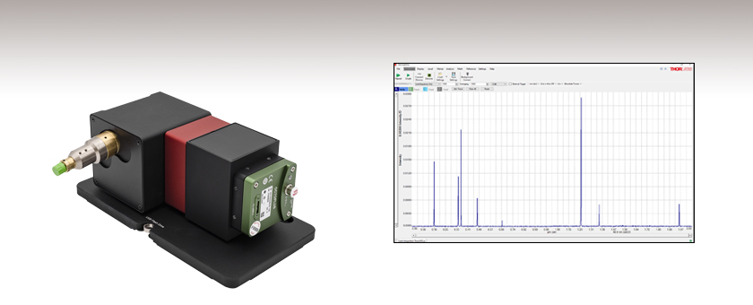
- Volume Phase Holographic Transmission Grating Design
- Up to 130 kHz Scan Rate
- External Trigger Input
- Wavelength Calibrated and Amplitude Corrected
HG10
Cables, Power Supply,
and Software Included
Spectrometer Software Included
Easy-to-Use Software Package with ThorSpectra GUI

Please Wait
Click to Enlarge
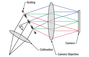
Diagram Showing the Operation of the HG10 Spectrometer
Features
- 810 - 965 nm Wavelength Range
- Incorporates a Volume Phase Holographic Transmission Grating
- Spot-Size-Limited Design (Diffraction-Limited with Single Mode Fiber Input)
- High-Speed USB 3.0 Connection Allows up to 130,000 Scans per Second
- Trigger Input for External Synchronization (TTL)
- 2048 Pixel Line Scan Sensor
- Wavelength Calibrated and Shipped with Calibration Report
- Amplitude Corrected: Relative Correction Based on Pixel Intensity
- Includes Single Mode Fiber Patch Cable
- Customizable Center Wavelength and Camera Speed (Please Contact our OCT Support Team)
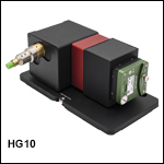
Thorlabs' HG10 Holographic Grating Spectrometer is a fiber-based, high-speed spectrometer that provides sub-nanometer resolution in the optical range of 810 to 965 nm. Its acquisition speed of up to 130 kHz, external synchronization options via a TTL trigger input, and rigid design make it ideal for stable and rapid spectrum acquisition. The spectrometer is based on the ones used in our Ganymede™ Series of Optical Coherence Tomography (OCT) imaging systems and has been designed to support easy integration into laboratory setups.
This device is a refraction-optics-based spectrometer. The incoming light is collimated to optimize the performance of the volume phase holographic (VPH) grating and guarantee that the light incident on the grating has a flat wavefront. The grating output angle depends on the wavelength, and this effect is used to create a spatial distribution of the spectrum on the camera, as seen in the diagram to the right.
Each spectrometer ships with a USB flash drive, an adapter cable for external trigger signals, a high-speed USB 3.0 cable, and a P3-780A-FC-2 single mode fiber optic patch cable with FC/APC connectors. The unit comes wavelength calibrated and amplitude corrected with the included patch cable prior to shipment. The included USB flash drive contains the software package, calibration report, and calibration certificate. Thorlabs offers a large selection of fiber optic patch cables and bundles that may be purchased separately. Please note that changing the fiber patch cable makes the calibration void; if a replacement or alternate patch cable is required, Thorlabs recommends recalibration using the new cable. Please contact oct@thorlabs.com if you are interested in a spectrometer calibrated with a different patch cable.
The performance data for each spectrometer can be downloaded by clicking on the red Docs icon (![]() ) next to the Item # and entering your device's serial number under "Download Calibration Data."
) next to the Item # and entering your device's serial number under "Download Calibration Data."
Mounting Options
For ease and stability of mounting, the HG10 spectrometer is equipped with a base plate. The base plate has three slots that allow the device to be mounted on standard imperial (1/4”-20 taps) and metric (M6 taps) breadboards and optical tables. If the spectrometer is used as a stand-alone device, four self-adhesive rubber feet are included and can be easily attached in the recesses on the bottom of the base plate. See the Setup tab for more details.
Software
The included software contains built-in tools for simple and complex analysis, including controls for adjusting sensitivity and resolution, a wavelength meter tool for narrowband sources, and a coherence length tool for broadband sources. Apodization functions, which are used to account for the finite path length over which the spectrum is measured, are also available. The ThorSpectra GUI can be used to view the spectra as they are being acquired. The raw data can be exported as is or with user-selected processing applied, including wavelength calibration, interpolation onto an evenly spaced wavelength grid, or relative amplitude correction. Please see the Software tab for additional details on software capabilities.
Custom Spectrometers
Custom spectrometers with detection ranges from 500 to 1000 nm are available. We are able to customize the camera speed from 20 to 250 kHz with a USB or CameraLink interface. Please contact oct@thorlabs.com if you are interested in a spectrometer with a different camera speed, camera interface, resolution, or optical fiber.
Recalibration Service
Thorlabs offers a recalibration service for the HG10 spectrometer (which can be ordered below using Item # CAL-HG). To ensure accurate measurements, we recommend recalibrating every twelve months.
Click to Enlarge
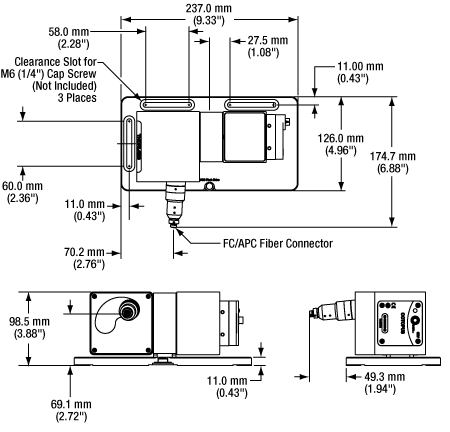
Mechanical Drawing for the HG10 Spectrometer
| Specifications | ||
|---|---|---|
| Optical | ||
| Detection Range (Typical) | 810 - 965 nm (12 346 - 10 363 cm-1) |
|
| Spectral Resolution (FWHM) | 0.25 nma (3.16 cm-1) |
|
| Spectral Accuracy | ±0.15 nma (±1.9 cm-1) |
|
| Pixel Resolutionb | 0.08 nm | |
| Wavelength Precision | ±0.1 nm | |
| Signal-to-Noise Ratio | 40 dB | |
| OCT A-Scan Resolution (FWHM)c | 5.0 µm | |
| OCT Imaging Depth | 2.5 mm | |
| Stray Lightd | <0.1% | |
| Included Patch Cable | ||
| Patch Cable Item # | P3-780A-FC-2e | |
| Fiber Item # | 780HP | |
| Connector | FC/APC, 2.0 mm Narrow Key | |
| Numerical Aperture | 0.13 | |
| Grating | ||
| Item # | GP3512N | |
| Type | Volume Phase Holographic Transmission | |
| Line Density | 1200 Lines/mm | |
| Design Wavelength | 930 nm | |
| Info | ||
| Camera | ||
| Sensor Type | Silicon | |
| Sensor Range | 400 - 1100 nm | |
| Interface | USB 3.0 | |
| Maximum Speed | 130 kHz | |
| Minimum Speed | 1.5 kHz | |
| Integration Time (Maximum) | 654.6 µs | |
| Acquisition Period (Maximum) | 655.35 µs | |
| Pixels/Line | 2048 | |
| Pixel Size | 10 µm x 200 µm | |
| Dynamic Range | 69 dB | |
| Analog-to-Digital Conversion (ADC) Resolution | 130 kHz @ 10 Bit <120 kHz @ 12 Bit |
|
| Readout Noise | 55 e- | |
| Full Well Capacity (Typical) | 140 ke- | |
| Quantum Efficiency Coefficient | 54% | |
| External Trigger | ||
| Maximum Frequency | 130 kHz | |
| Input Interface | BNC | |
| Signal | TTL | |
| Input Voltage | 0 - 5 V | |
| General | ||
| Interface to PC | USB 3.0 | |
| Dimensions (L x W x H), Without Cable and Fiber | 237.0 mm x 174.7 mm x 98.5 mm (9.33" x 6.88" x 3.88") |
|
| Weight (Spectrometer Only) | 2.9 kg | |
| Ambient Operating Temperature | 10 °C to 35 °C (Non-Condensing) | |
Mounting Options
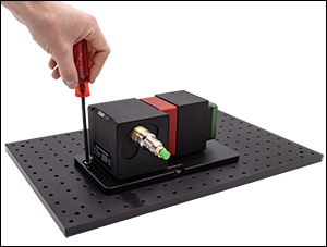
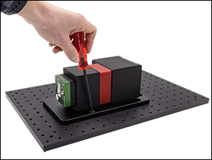
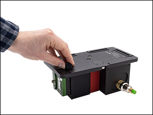
For mounting ease and stability, the HG10 spectrometer is equipped with a base plate. The base plate has three slots that allow the device to be mounted on standard imperial (1/4”-20 taps) and metric (M6 taps) breadboards and optical tables. For optimal stability, use multiple slots to secure your device. If the spectrometer is being used as a stand-alone device, four self-adhesive rubber feet are included and can be attached easily in the recesses on the base plate’s bottom side.
Click to Enlarge
Breadboard Mounting, Step 1: Mount the unit on a breadboard such as the MB3045/M Breadboard above using the slot on the back.
Click to Enlarge
Breadboard Mounting, Step 2: Secure the unit on the breadboard using one or more of the slots on the side.
Click to Enlarge
For Stand-Alone Operation: Attach the self-adhesive rubber feet to the bottom of the spectrometer.
Connecting the Spectrometer
Detailed instructions to connect the spectrometer are provided in each manual (included with each device and accessible by clicking on the red documents icon below).
Click to Enlarge
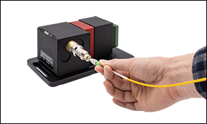
Step 1: Connect the included FC/APC fiber to the spectrometer.
Click to Enlarge
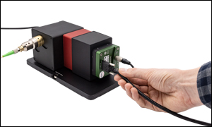
Step 2: Connect the power supply and wait until the Camera LED turns green. Then connect the USB 3.0 cable to the spectrometer and the PC.
Click to Enlarge
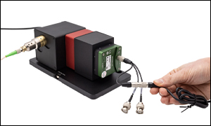
Step 3: If needed, connect the trigger adapter cable to use an external trigger or to read the internal camera trigger.
Item # HG10 includes the following:
- Holographic Grating Spectrometer
- Power Supply with Region-Specific Power Cord
- Trigger Cable Adapter, 20 cm
- BNC Straight Adapter (Item # T3283)
- Single Mode Optical Fiber with FC/APC Connector, 2 m (Item # P3-780A-FC-2)
- USB 3.0 Cable Type A/B Micro Cable, 2 m
- USB Flash Drive
- Four Rubber Feet
- Quick Start Guide
Software
Version 1.0.2.28
Software package to operate the HG10 Spectrometer including the ThorSpectra GUI, drivers, and SDKs for third-party development.
Click to Enlarge
Software GUI
Software for the HG10 Spectrometer
- Operates up to 10 Devices Simultaneously
- Auto-Detection of Compatible Devices
- Available Filters: Peak Finder, Smoothing, Averaging, Flip/Revert Picture
- Algorithms: Gaussian Transformation, Absorbance, Transmittance and Relative Difference Measurement
- Normalized Y Axis
- Persistence Option
- User Wavelength Calibration
- Optional Amplitude Correction
- User-Selectable Colors and Shapes
- Saving and Retrieval of Scans (.spf2 or .csv)
- Copy to Clipboard Function
- Printable Windows
- Tabbed or Floating Windows
- Polynomial or Gaussian Data Fitting
- Adjustable Parameters:
- Integration Time
- Trigger Modes: Internal, External, Continuous, Single Shot
- Averaging Method: Gliding or Block Average
- Smoothing Method: Block Smoothing
- Picture Flip and Revert
- Display Mode: nm or Pixel
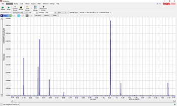
The HG Software Package, designed for laboratory and manufacturing applications, features the easy-to-use ThorSpectra graphical user interface (GUI). The GUI allows multiple sets of data to be displayed in a single graph for comparison with each other and the background data. With the help of smoothing and averaging algorithms, the user is able to enhance specific features of the spectra. Furthermore, the software is able to control up to ten devices at one time and present the data in a single graph.
The screenshot to the right shows the peaks from a calibration lamp acquired with the HG10 spectrometer. The peaks show the specific wavelengths emitted by the calibration lamp.
Additionally, Thorlabs provides drivers for C, C++, C#, MATLAB, Python, and LabVIEW for more specific demands. The software package supports LabVIEW from version 2017 onwards. Code from earlier versions of LabView will need to be converted to a newer format; if assistance with the conversion is needed, please contact the OCT Support Team.
Data Processing
The software allows stored data to be loaded for comparison. Absorbance, transmittance, or the relative difference can be calculated and displayed.
Software Development Kits (SDKs)
For maximum flexibility, the HG Software offers several possibilities to implement customized solutions using software development kits (SDKs). The libraries can be used in a multitude of programming environments (C, C++, C#, MATLAB, Python, and LabVIEW) and allow the user to directly control the HG system, implement customized data acquisition routines, and execute spectral processing functions. For more information on the architecture of the SDKs, please see the manual.
To facilitate the use and integration of the HG spectrometer all SDKs include code examples covering various scenarios and use cases. The sample programs are commented step by step and are an excellent starting position to develop user defined applications. Besides fundamental functions, regarding initialization, logging and error handling, the examples demonstrate how to:
- Modify Device Parameters
- Acquire and Process a User-Selected Number of Raw Spectra
- Continuously Acquire and Process Data
- Acquire Data at a Specific Line Rate or Exposure Time
- Use Callbacks to Acquire Data
- Write Data Directly to a File or a Sequence of Files
- Use an External Trigger
Please contact oct@thorlabs.com for details.
Diffraction Gratings Tutorial
- Introduction
- Blazed (Ruled) Gratings
- Volume Phase Holographic Transmission Gratings
- Holographic Reflective Gratings
Introduction
Diffraction gratings, either transmissive or reflective, can separate different wavelengths of light using a repetitive structure embedded within the grating. The structure affects the amplitude and/or phase of the incident wave, causing interference in the output wave. In the transmissive case, the repetitive structure can be thought of as many tightly spaced, thin slits. Solving for the irradiance as a function wavelength and position of this multi-slit situation, we get a general expression that can be applied to all diffractive gratings when = 0°,

(1)
known as the grating equation. The equation states that a diffraction grating with spacing will deflect light at discrete angles (
), dependent upon the value
λ, where
is the order of principal maxima. The diffracted angle,
, is the output angle as measured from the surface normal of the diffraction grating. It is easily observed from Eq. 1 that for a given order
, different wavelengths of light will exit the grating at different angles. For white light sources, this corresponds to a continuous, angle-dependent spectrum.
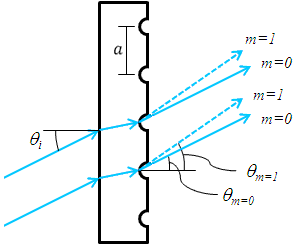
Figure 1. Transmission Grating
Transmission Gratings
One popular style of grating is the transmission grating. The sample diffraction grating with surfaces grooves shown in Figure 1 is created by scratching or etching a transparent substrate with a repetitive series of narrow-width grooves separated by distance . This creates areas where light can scatter.
The incident light impinges on the grating at an angle , as measured from the surface normal. The light of order
exiting the grating leaves at an angle of
, relative to the surface normal. Utilizing some geometric conversions and the general grating expression (Eq. 1) an expression for the transmissive diffraction grating can be found:

(2)
where both and
are positive if the incident and diffracted beams are on opposite sides of the grating surface normal, as illustrated in the example in Figure 1. If they are on the same side of the grating normal,
must then be considered negative.
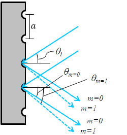
Figure 2. Reflective Grating
Reflective Gratings
Another very common diffractive optic is the reflective grating. A reflective grating is traditionally made by depositing a metallic coating on an optic and ruling parallel grooves in the surface. Reflective gratings can also be made of epoxy and/or plastic imprints from a master copy. In all cases, light is reflected off of the ruled surface at different angles corresponding to different orders and wavelengths. An example of a reflective grating is shown in Figure 2. Using a similar geometric setup as above, the grating equation for reflective gratings can be found:

(3)
where is positive and
is negative if the incident and diffracted beams are on opposite sides of the grating surface normal, as illustrated in the example in Figure 2. If the beams are on the same side of the grating normal, then both angles are considered positive.
Both the reflective and transmission gratings suffer from the fact that the zeroth order mode contains no diffraction pattern and appears as a surface reflection or transmission, respectively. Solving Eq. 2 for this condition, =
, we find the only solution to be
=0, independent of wavelength or diffraction grating spacing. At this condition, no wavelength-dependent information can be obtained, and all the light is lost to surface reflection or transmission.
This issue can be resolved by creating a repeating surface pattern, which produces a different surface reflection geometry. Diffraction gratings of this type are commonly referred to as blazed (or ruled) gratings. More information about this can be found in the section below.
Blazed (Ruled) Gratings
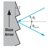
Figure 4. Blazed Grating, 0th Order Reflection
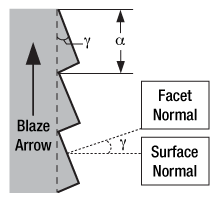
Figure 3. Blazed Grating Geometry
The blazed grating, also known as the echelette grating, is a specific form of reflective or transmission diffraction grating designed to produce the maximum grating efficiency in a specific diffraction order. This means that the majority of the optical power will be in the designed diffraction order while minimizing power lost to other orders (particularly the zeroth). Due to this design, a blazed grating operates at a specific wavelength, known as the blaze wavelength.
The blaze wavelength is one of the three main characteristics of the blazed grating. The other two, shown in Figure 3, are , the groove or facet spacing, and
, the blaze angle. The blaze angle
is the angle between the surface structure and the surface parallel. It is also the angle between the surface normal and the facet normal.
The blazed grating features geometries similar to the transmission and reflection gratings discussed thus far; the incident angle () and
th order reflection angles (
) are determined from the surface normal of the grating. However, the significant difference is the specular reflection geometry is dependent on the blaze angle,
, and NOT the grating surface normal. This results in the ability to change the diffraction efficiency by only changing the blaze angle of the diffraction grating.
The 0th order reflection from a blazed grating is shown in Figure 4. The incident light at angle is reflected at
for
= 0. From Eq. 3, the only solution is
= –
. This is analogous to specular reflection from a flat surface.
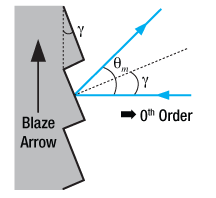
Figure 6. Blazed Grating, Incident Light Normal to Grating Surface
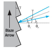
Figure 5. Blazed Grating, Specular Reflection from Facet
The specular reflection from the blazed grating is different from the flat surface due to the surface structure, as shown in Figure 5. The specular reflection, , from a blazed grating occurs at the blaze angle geometry. This angle is defined as being negative if it is on the same side of the grating surface normal as
. Performing some simple geometric conversions, one finds that

(4)
Figure 6 illustrates the specific case where = 0°, hence the incident light beam is perpendicular to the grating surface. In this case, the 0th order reflection also lies at 0°. Utilizing Eqs. 3 and 4, we can find the grating equation at twice the blaze angle:

(5)
Littrow Configuration for Reflective Gratings
The Littrow configuration refers to a specific geometry for blazed gratings and plays an important role in monochromators and spectrometers. It is the angle at which the grating efficiency is the highest. In this configuration, the angle of incidence of the incoming and diffracted light are the same,
=
, and
> 0 so

(6)
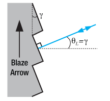
Figure 7. Littrow Configuration
The Littrow configuration angle, , is dependent on the most intense order (
= 1), the design wavelength,
, and the grating spacing
. It is easily shown that the Littrow configuration angle,
, is equal to the blaze angle,
, at the design wavelength. The Littrow / blaze angles for all Thorlabs' Blazed Gratings can be found in the grating specs tables.

(7)
It is easily observed that the wavelength dependent angular separation increases as the diffracted order increases for light of normal incidence (for = 0°,
increases as
increases). There are two main drawbacks for using a higher order diffraction pattern over a low order one: (1) a decrease in efficiency at higher orders and (2) a decrease in the free spectral range,
![]() , defined as:
, defined as:

(8)
where is the central wavelength, and
is the order.
The first issue with using higher order diffraction patterns is solved by using an Echelle grating, which is a special type of ruled diffraction grating with an extremely high blaze angle and relatively low groove density. The high blaze angle is well suited for concentrating the energy in the higher order diffraction modes. The second issue is solved by using another optical element: grating, dispersive prism, or other dispersive optic, to sort the wavelengths/orders after the Echelle grating.
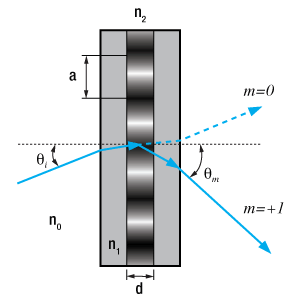
Figure 8. Volume Phase Holographic Grating
Volume Phase Holographic Transmission Gratings
Unlike traditional gratings, volume phase holographic (VPH) gratings do not have surface grooves. Instead, VPH gratings consist of a dichromated gelatin (DCG) film between two glass substrates. These VPH gratings are designed to reduce the periodic errors that can occur in blazed gratings. Surface gratings with high groove density also have an issue with polarization dependent loss. These unique transmission gratings deliver high first-order diffraction peak efficiency, low polarization dependence, and uniform performance over broad bandwidths.
The desired grating pattern is comprised of a repetitive series of lines separated by distance . The fringe planes for transmission gratings are perpendicular to the plane of the plate as seen in Figure 8, allowing any frequency of light to pass through the plate. Diffraction occurs as incoming light crosses through the DCG film. Therefore, the three major factors that determine performance are film thickness, bulk index (the average index of refraction between Bragg planes), and index modulation (the difference of index of refraction between the Bragg planes). The incident light enters the grating at an angle of
, as measured from the surface normal. The light of order
exiting the grating leaves at an angle of
, relative to the surface normal. The grating expression mentioned above can be used to calculate diffraction angles for volume phase holographic gratings since dispersion is based on the line density. The quality of the grating is determined by the fringe contrast, with a poor fringe contrast resulting in low efficiency or no grating at all.
The DCG film is taken through multiple quality control steps to ensure it performs up to standard and then cut into the desired size. The film is sealed between two glass covers to prevent degradation of the material. Since the DCG film is contained between two glass substrates, VPH gratings have high durability and long lifetimes, as well as easy maintenance compared to other gratings that can be easily damaged.
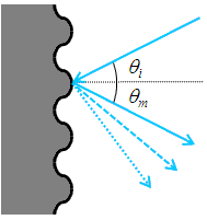
Figure 9. Holographic Grating
Holographic Surface Reflective Gratings
While blazed gratings offer extremely high efficiencies at the design wavelength, they suffer from periodic errors, such as ghosting, and relatively high amounts of scattered light, which could negatively affect sensitive measurements. Holographic gratings are designed specially to reduce or eliminate these errors. The drawback of holographic gratings compared to blazed gratings is reduced efficiency.
Holographic gratings are made from master gratings by similar processes to the ruled grating. The master holographic gratings are typically made by exposing photosensitive material to two interfering laser beams. The interference pattern is exposed in a periodic pattern on the surface, which can then be physically or chemically treated to expose a sinusoidal surface pattern. An example of a holographic grating is shown in Figure 9.
Please note that dispersion is based solely on the number of grooves per mm and not the shape of the grooves. Hence, the same grating equation can be used to calculate angles for holographic as well as ruled blazed gratings.
| Posted Comments: | |
| No Comments Posted |

- 810 - 965 nm Operating Wavelength Range
- 2.0 mm Narrow-Key FC/APC Connector
- Acquire Spectra at a Rate up to 130 kHz
The HG10 Holographic Grating Spectrometer is a fiber-based, high-speed spectrometer that provides sub-nanometer resolution. Each spectrometer is wavelength calibrated and amplitude corrected relative to the pixel intensity with its included patch cable, and a calibration report is included on the USB stick shipped with each unit. Note that if a different patch cable is used with the spectrometer, the system (spectrometer and new patch cable) should be recalibrated.
Thorlabs offers a recalibration service for the HG10 spectrometer, which can be ordered below (see Item # CAL-HG).

Thorlabs offers a recalibration service for our HG10 Holographic Grating Spectrometer. To ensure accurate measurements, we recommend recalibrating the spectrometer every 12 months. When sending the part for recalibration, please include the patch cable that the spectrometer will be used with.
Requesting a Calibration
Thorlabs provides two options for requesting a calibration:
- Complete the Returns Material Authorization (RMA) form. When completing the RMA form, please enter your name, contact information, the Part #, and the Serial # of the spectrometer being returned for calibration; in the Reason for Return field, select "I would like an item to be calibrated." If you wish to calibrate your spectrometer with a different patch cable than the one that came with the unit, please list the patch cable Item # in the Further Details field. All other fields are optional. Once the form has been submitted, a member of our RMA team will reach out to provide an RMA Number, return instructions, and to verify billing and payment information.
- Enter the Part # and Serial # of the item that requires recalibration below and then Add to Cart. A member of our RMA team will reach out to coordinate the return of the item(s) for calibration. Should you have other items in your cart, note that the calibration request will be split off from your order for RMA processing.
Please Note: To ensure your item being returned for calibration is routed appropriately once it arrives at our facility, please do not ship it prior to being provided an RMA Number and return instructions by a member of our team.
 Products Home


 Zoom
Zoom Holographic Grating Spectrometer