10 mm (0.39") Travel or Less Motorized Actuators
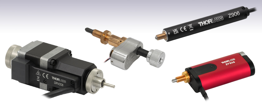
- High-Resolution Piezo Inertia, Stepper, and DC Servo Actuators
- Compatible with a Wide Range of Stages
- Velocities up to 5 mm/s
PIAK10VF
10 mm Travel
Piezo Inertia Actuator,
Vacuum Compatible
Z906
6 mm Travel, DC Actuator
DRV208
8 mm Travel,
Stepper Motor Actuator
ZFS06
6 mm Travel, Compact
Stepper Motor Actuator

Please Wait

Required Controller:
KST201
- 49,152 Microsteps per Revolution
- 15 V Output at 12 W
- Trapezoidal and
'S-Curve' Velocity Profiles
Features
- Compact Package: 86.5 mm (3.40") Long, Fully Retracted
- Manual Adjustment via Rear-Located Thumbscrew
- Non-Rotating Drive Tip
- Compatible with Mirror Mounts and Translation Stages with 1/4"-80 Threads
- Also Available in 13 mm and 25 mm Travel Versions
Our ZFS06 Motorized Actuator provides smooth, precise linear motion control in a sleek, compact package measuring just 86.5 mm (3.40") in length when fully retracted. This compact profile reduces the distance between the end of the actuator and optomechanical components, keeping the center of mass closer to the contact point than the ZST206 actuator featured above. This actuator has a 1/4"-80 threaded barrel that can be mounted to any manual mirror mount or positioning stage equipped with 1/4"-80 threads.
Powered by a small-diameter, two-phase, bi-polar stepper motor, this actuator operates at speeds of up to 2.0 mm/s. The non-rotating drive tip reduces wear and friction and improves smoothness of motion by removing rotational contact at the tip. If power is not supplied to the actuator, manual adjustment is achievable using the rear-located thumbscrew. The actuator motor can be damaged if this thumbscrew is rotated while power is being supplied to the motor.
Our ZFS06 actuator incorporates a stepper motor that provides sufficient torque for loads up to 40 N (8.99 lbs). The actuator allows for very small step sizes over the entire travel range, delivering greater flexibility with low (<15 µm) backlash and fine resolution. The design incorporates a 400:9 gear reduction head which, when combined with the 49,152 microsteps per revolution offered by the KST201 stepper motor driver, gives a theoretical travel per microstep of 0.46 nm (see the Calculations tab for details).
| Item # | ZFS06 |
|---|---|
| Travel | 6 mm (0.24") |
| Backlasha | <15 µm |
| Bidirectional Repeatability | <5.0 µm |
| Home Location Accuracy | <5.0 µm |
| Maximum Load Capacity | 40 N (8.99 lbs) |
| Velocity | 2.0 mm/s (Max) |
| Acceleration | 10 mm/s2 (Max) |
| Gearbox Ratio | 400:9 (Approx. 44:1) |
| Limit Switches | Hall Effect |
| Lead Screw Pitch | 1.0 mm |
| Motor Type | 2-Phase Stepper |
| Microsteps per Revolution of the Motorb | 24 Full Steps, 2048 µsteps per Full Step 49,152 µsteps per Revolution |
| Calculated Minimum Incremental Motionc | 0.46 nm |
| Operating Temperature | 5 to 40 °C (41 to 104 °F) |
| Dimensions (L x W x H) | 86.5 mm x 35.0 mm x 19.0 mm (3.40" x 1.38" x 0.75") |
| Cable Length | 0.6 m (2 ft) |
| Connector | HDDB15 |
| Required Controller | KST201 |
Hall effect limit switches prevent the unit from being overdriven and provide homing capability with an accuracy of <5.0 μm. The ZFS series actuators come with 0.6 m (2 ft) of cable terminated in a 15-pin D-Type connector (see the Pin Diagrams tab) that is compatible with our KST201 stepper motor controller. A 1 m (3.3 ft) extension cable (PAA614) is available separately.
The ZFS06 has been designed specifically to replace the manual adjusters in stages and mirror mounts that have 1/4"-80 threaded fittings, particularly in applications where space is tight. Simply remove the existing manual adjuster from the mount and screw in the ZFS06 actuator. Two ZFS06 motorized actuators replace the thumbscrews of the KM100 in the image below.
How to calculate the linear displacement per microstep
The ZFS series of motors has 24 full steps per revolution, and when driven by the KST201 drivers, there are 2048 microsteps per full step, giving 49,152 microsteps per revolution of the motor. The output shaft of the motor goes into a 400:9 gear head. This requires the motor to rotate 44.445 times to rotate the 1.0 mm pitch lead screw one revolution. The end result is the lead screw advances by 1.0 mm.
Linear displacement of the lead screw per microstep:
Number of Microsteps x Gearbox Ratio = 49,152 x 44.445 = 2184560.64
The linear displacement of the lead screw per microstep is
1.0 mm / 2184560.64 = 0.46 x 10⁻⁶ mm = 0.46 nm
Pin Diagram

High-Density D-Type Male 15 Pin Connector
Connector Pin Out
| Pin | Description | Pin | Description |
|---|---|---|---|
| 1 | Limit Ground | 8 | Reserved for Future Use |
| 2 | CCW Limit Switch | 9 | Reserved for Future Use |
| 3 | CW Limit Switch | 10 | Vcc (+5 VDC) |
| 4 | Motor Phase B - | 11 | Reserved for Future Use |
| 5 | Motor Phase B + | 12 | Reserved for Future Use |
| 6 | Motor Phase A - | 13 | Reserved for Future Use |
| 7 | Motor Phase A + | 14 | Reserved for Future Use |
| - | - | 15 | Ground |
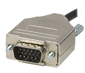
Click to Enlarge
High-Density D-Type Male 15 Pin Connector
| Posted Comments: | |
Franklin Wei
(posted 2022-12-05 00:17:39.137) Is there an equivalent of ZFS06 which can be fitted to an SCP05 X-Y 0.5" translation mount? Our application requires a very compact actuator with 1mm of travel in X and Y for automatic confocal pinhole alignment. DJayasuriya
(posted 2022-12-05 10:59:25.0) Thank you for your inquiry. Unfortuantely we dont have cage mounts that would work with actuators yet. We have got in touch with you directly to discuss your application. |

Required Controller:
KST201
- 49,152 Microsteps per Revolution
- 15 V Output at 12 W
- Trapezoidal and
'S-Curve' Velocity Profiles
Features
- Non-Rotating Drive Tip
- Bi-Polar Stepper Motor Actuator: 111.0 mm (4.37") Long
- 1/4"-80 Threaded Barrel Mounting
- Compatible with Mirror Mounts and Translation Stages with 1/4"-80 Threads
- Also Available in 13 mm and 25 mm Travel Versions
Our ZST series actuators provide smooth, precise linear motion control in a package measuring 111.0 mm (4.37") in length. Powered by a small-diameter, two-phase, bi-polar stepper motor, this actuator operates at speeds of up to 2.0 mm/s. The non-rotating drive tip reduces wear and friction and improves smoothness of motion by removing rotational contact at the tip. This actuator has a 1/4"-80 threaded barrel that can be mounted to any manual mirror mount or positioning stage equipped with 1/4"-80 threads.
Our ZST200 line of actuators all incorporate a stepper motor that provides sufficient torque for loads up to 40 N (8.99 lbs). The actuator allows for very small step sizes over the entire travel range, delivering greater flexibility with low (<15 µm) backlash and fine resolution. The design incorporates a 41:1 gear reduction head which, when combined with the 49,152 microsteps per revolution offered by the KST201 stepper motor driver, gives a theoretical travel per microstep of 0.5 nm (see the Calculations tab for details).
| Item # | ZST206 |
|---|---|
| Travel | 6 mm (0.24") |
| Backlasha | <15 µm |
| Bidirectional Repeatability | <5.0 µm |
| Home Location Accuracy | <5.0 µm |
| Maximum Load Capacity | 40 N (8.99 lbs) |
| Velocity | 2.0 mm/s (Max) |
| Acceleration | 10 mm/s2 (Max) |
| Gearbox Ratio | 29791:729 (Approx. 41:1) |
| Limit Switches | Hall Effect |
| Lead Screw Pitch | 1.0 mm |
| Motor Type | 2-Phase Stepper |
| Microsteps per Revolution of the Motorb | 24 Full Steps, 2048 µsteps per Full Step 49,152 µsteps per Revolution |
| Calculated Minimum Incremental Motion | 0.5 nm |
| Operating Temperature | 5 to 40 °C (41 to 104 °F) |
| Dimensions (L x W) | 111.0 mm x 19.0 mm (4.37" x 0.75") |
| Cable Length | 0.6 m (2 ft) |
| Connector | HDDB15 |
| Required Controller | KST201 |
Hall effect limit switches prevent the unit from being overdriven and provide homing capability with an accuracy of <5.0 μm. This actuator comes with 0.6 m (2 ft) of cable terminated in a 15-pin D-Type connector that is compatible with our KST201 stepper motor controller. A 1 m (3.3 ft) extension cable (PAA614) is available separately.
The ZST206 has been designed specifically to replace the manual adjusters in stages and mirror mounts that have 1/4"-80 threaded fittings. Simply remove the existing manual adjuster from the mount and screw in the ZST206 actuator.
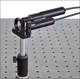
Click to Enlarge
A KM100 mirror mount with the screw adjusters replaced by two ZST206 actuators.
How to calculate the linear displacement per microstep
Each member of the ZST200 series of motors has 24 full steps per revolution, and when driven by the KST201 drivers, there are 2048 microsteps per full step. Hence, there are 49,152 microsteps per revolution of the motor. The output shaft of the motor goes into a 40.866:1 gear head. This requires the motor to rotate 40.866 times to rotate the 1.0 mm pitch lead screw one revolution. The end result is the lead screw advances by 1.0 mm. To calculate the linear displacement of the actuator per microstep, use the following:
Linear displacement of the lead screw per microstep:
Number of Microsteps x Gearbox Ratio = 49,152 x 40.866 = 2,008,645.63
The linear displacement of the lead screw per microstep is
1.0 mm / 2,008,645.63 = 0.49 x 10⁻⁶ mm = 0.5 nm
Pin Diagram

High-Density D-Type Male 15 Pin Connector
Connector Pin Out
| Pin | Description | Pin | Description |
|---|---|---|---|
| 1 | Limit Ground | 8 | Reserved for Future Use |
| 2 | CCW Limit Switch | 9 | Reserved for Future Use |
| 3 | CW Limit Switch | 10 | Vcc (+5 VDC) |
| 4 | Motor Phase B - | 11 | Reserved for Future Use |
| 5 | Motor Phase B + | 12 | Reserved for Future Use |
| 6 | Motor Phase A - | 13 | Reserved for Future Use |
| 7 | Motor Phase A + | 14 | Reserved for Future Use |
| - | - | 15 | Ground |

Click to Enlarge
High-Density D-Type Male 15 Pin Connector
| Posted Comments: | |
| No Comments Posted |

Required Controller:
KDC101
- 34,555 Microsteps per Revolution
- 15 V Output at 2.5 W
- Trapezoidal Velocity Profile
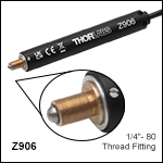
| Item # | Z906 |
|---|---|
| Travel Range | 6 mm (0.24") |
| Encoder Resolutiona | 34,555 counts/mm (Linear Displacement) |
| Maximum Pushing Force | 45 N |
| Homing Repeatability | ±5 µm |
| Uncompensated Backlash | 6 µm |
| Uncompensated Bidirectional Repeatability | ±3 µm |
| Residual Backlash After Compensationb | 0.1 µm |
| Compensated Bidirectional Repeatability | ±0.3 µm |
| Travel Accuracyc | 6 µm |
| Minimum Repeatable Incremental Movement | 0.2 µm |
| Maximum Speedd | 2.6 mm/s |
| Maximum Acceleration | 4 mm/s2 |
| Maximum Phase to Phase Resistance | 33.0 Ω |
| Maximum Phase to Phase Inductance | 0.6 mH |
| Tested Lifetimee | >100,000 Cycles |
| Operating Temperature Range | 41° to 104° F (5° to 40° C) |
| Weight | 0.13 kg |
| Motor Typef | DC Servo |
| Cable Length | 485.0 mm (19.09") |
| Required Controller | KDC101 |
Features
- DC Servo Actuator
- Sub-Micron Resolution
- Maximum Operating Speed: 2.6 mm/s
- Drop-In Replacement for Most 6 mm Manual Actuators
- Compatible with 1/4"-80 Thread-Fitting Stages and Mounts
- Limit Switches for Zero Datum and Actuator Protection
- Also Available in 12 mm and 25 mm Travel Versions
Thorlabs' Z906 motorized actuators are engineered for use with optical positioning devices such as mirror mounts and stages. They offer high resolution in a lightweight package, which makes these actuators ideally suited for demanding optical laboratory automation applications.
Electromechanical limit switches provide overdrive protection and accurate home positioning. The incorporated motor is capable of speeds up to 2.6 mm/s, but a maximum operating speed of 2.3 mm/s is recommended to maintain the specified control. The precision of the encoder (512 counts per motor revolution) results in a minimum resolution of about 29 nm. See Calculations tab for details.
The Z906 has been designed specifically to replace the manual adjusters in stages and mirror mounts that have 1/4"-80 threaded fittings. Simply remove the existing manual adjuster from the mount, and screw in the actuator. The image below shows a KM100 mirror mount with one of the screw adjusters replaced by a Z906 actuator. The units are shipped with one 485 mm (1.6') cable. A 2.5 m (8 ft) extension cable (Item # PAA632) is available separately.
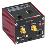
The KDC101 DC Servo Controller is the required driver for the Z9 series actuators. The latest version of the Kinesis software can be downloaded here. Firmware version 2.2.8 or higher, included in the Kinesis software version 1.14.40 or higher download, is required for using the KDC101 with the Z9 actuators. Prior versions of firmware will operate the Z9 actuators but will call the actuators Z8.
For applications with longer travel requirements, see our 12 mm travel Z912 and 25 mm travel Z925 actuators. We also offer the Z906V vacuum-compatible version, which is rated for use down to 10-6 torr and is shipped with a 1.6' flat ribbon cable, IDC connector, and converter cable for use with the KDC101 controller. See below for more details.
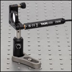
Click to Enlarge
A KM100 mirror mount with one screw adjuster replaced with Z906 actuator.
Pin Diagram

High-Density D-Type Male 15 Pin Connector
Connector Pin Out
| Pin | Description | Pin | Description |
|---|---|---|---|
| 1 | Ground (Limit and Vcc) | 9 | Resistive Identification |
| 2 | Forward Limit | 10 | +5 VDC |
| 3 | Reverse Limit | 11 | Encoder Channel A |
| 4 | Reserved for Future Use | 12 | Reserved for Future Use |
| 5 | Motor (-) | 13 | Encoder Channel B |
| 6 | Reserved for Future Use | 14 | Pin 2 Ident EEPROM |
| 7 | Motor (+) | 15 | Pin 1 Ident EEPROM |
| 8 | Reserved for Future Use |

Click to Enlarge
High-Density D-Type Male 15 Pin Connector
How to Calculate the Linear Displacement per Encoder Count
For the Z906, there are 512 encoder counts per revolution of the motor. The output shaft of the motor goes into a 67.49:1 planetary gear head. This requires the motor to rotate 67.49 times to rotate the 1.0 mm pitch lead screw one revolution. The end result is the lead screw advances by 1.0 mm.
The linear displacement of the actuator per encoder count is given by
512 x 67.49 = 34,555 encoder counts per revolution of the lead screw,
whereas the linear displacement of the lead screw per encoder count is given by
1.0 mm / 34,555 counts = 2.9 x 10⁻⁵ mm (29 nm).
| Posted Comments: | |
| No Comments Posted |

| Item # | Z906V |
|---|---|
| Travel Range | 6 mm (0.24") |
| Encoder Resolutiona | 34,555 counts/mm (Linear Displacement) |
| Maximum Pushing Force | 45 N |
| Homing Repeatability | ±5 µm |
| Uncompensated Backlash | 6 µm |
| Uncompensated Bidirectional Repeatability | ±3 µm |
| Residual Backlash After Compensationb | 0.1 µm |
| Compensated Bidirectional Repeatability | ±0.3 µm |
| Travel Accuracyc | 6 µm |
| Minimum Repeatable Incremental Movement | 0.2 µm |
| Maximum Speedd | 2.6 mm/s |
| Maximum Acceleration | 4 mm/s2 |
| Maximum Phase to Phase Resistance | 33.0 Ω |
| Maximum Phase to Phase Inductance | 0.6 mH |
| Tested Lifetimee | >100,000 Cycles |
| Operating Temperature Range | 41° to 104° F (5° to 40° C) |
| Vacuum Rating | 10-6 Torr |
| Weight | 80 g |
| Motor Typef | DC Servo |
| Cable Length | 485.0 mm (19.09") |
| Required Controller | KDC101 |
Features
- 6 VDC Servo Actuator
- Sub-Micron Resolution
- Maximum Operating Speed: 2.6 mm/s
- Drop In Replacement for Most 6 mm Manual Actuators
- Compatible with 1/4"-80 Thread-Fitting Stages and Mounts
- Limit Switches for Zero Datum and Actuator Protection
- Vacuum-Rated to 10-6 Torr
- Also Available in 12 mm and 25 mm Travel Versions
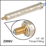
The Z906V actuator offers features and specifications similar to the Z906 actuator described above with the added benefit of being vacuum compatible down to 10-6 Torr. It incorporates vacuum-rated servo motors, a phosphorus bronze internal coupling mechanism and mounting bush, and high-vacuum grease.
The Z906V actuator is shipped with a 485 mm (1.6') vacuum-compatible flat ribbon cable with an IDC connector. This cable has 1.27 mm (0.05") pitch, 28 AWG stranded conductors and fluorinated ethylene propylene (FEP) insulation. A converter cable for use with the KDC101 controller is also supplied, but it is not vacuum compatible and should only be used outside the chamber.
The KDC101 DC Servo Controller is the required driver for the Z9 series actuators. The latest version of the Kinesis software can be downloaded here. Firmware version 2.2.8 or higher and Kinesis software version 1.14.44 or higher are required for using the KDC101 with the Z9 vacuum-compatible actuators.
For applications with longer travel requirements, see our 12 mm travel Z912V and 25 mm travel Z925BV actuators. For vacuum compatible versions of our stages and mirror mounts, please contact Tech Support.
Required Controller:
KDC101
- 34,555 Microsteps per Revolution
- 15 V Output at 2.5 W
- Trapezoidal Velocity Profile
How to Calculate the Linear Displacement per Encoder Count
For the Z906V, there are 512 encoder counts per revolution of the motor. The output shaft of the motor goes into a 67.49:1 planetary gear head. This requires the motor to rotate 67.49 times to rotate the 1.0 mm pitch lead screw one revolution. The end result is the lead screw advances by 1.0 mm.
The linear displacement of the actuator per encoder count is given by
512 x 67.49 = 34,555 encoder counts per revolution of the lead screw,
whereas the linear displacement of the lead screw per encoder count is given by
1.0 mm / 34,555 counts = 2.9 x 10⁻⁵ mm (29 nm).
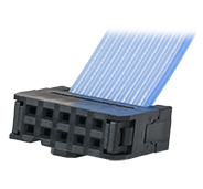
The vacuum-compatible cable integrated with the Z906V actuator is terminated in a female IDC 10-Pin socket connector. A short converter cable, which adapts this female IDC socket connector to a D-type male HD15 pin connector, is included with the Z906V actuator to facilitate connecting it to the recommended KDC101 controller. This converter cable, whose terminating connectors are shown below, is not vacuum compatible. Information describing the pin assignments for both the female IDC socket and male D-type HD connector (when it is connected to the female IDC socket connector) follows.
Pin Diagram
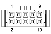
10 Pin Female IDC Socket Connector
(Amphenol T812 Series, 2.54 mm Pitch)
Female IDC 10-Pin Connector Pin Out
| Pin | Description | Pin | Description |
|---|---|---|---|
| 1 | Motor (+) | 6 | Motor (-) |
| 2 | Vcc | 7 | Limit Ground |
| 3 | Channel A | 8 | Reverse Limit |
| 4 | Channel B | 9 | Forward Limit |
| 5 | Ground | 10 | Not Connected |
Pin Diagram

High-Density D-Type Male 15 Pin Connector
Male HDDB15 Connector Pin Out
| Pin | Description | Pin | Description |
|---|---|---|---|
| 1 | Ground (Limit and Vcc) | 8 | Reserved For Future Use |
| 2 | Forward Limit | 9 | Ident Resistor |
| 3 | Reverse Limit | 10 | Vcc (+5 VDC) |
| 4 | Reserved For Future Use | 11 | Encoder Channel A |
| 5 | Motor (-) | 12 | Reserved for Future Use |
| 6 | Reserved for Future Use | 13 | Encoder Channel B |
| 7 | Motor (+) | 14, 15 | Reserved For Future Use |

Click to Enlarge
Connectors terminating the converter cable. The image on the left shows the high-density D-type male 15-pin connector, and the image on the right shows the 10-pin male IDC socket connector.
| Posted Comments: | |
| No Comments Posted |

Compatible Controller:
BSC201
- 409,600 Microsteps per Revolution
- 48 V Output at 25 W
- Trapezoidal and
'S-Curve' Velocity Profile
| Item # | DRV208 |
|---|---|
| Travel | 8 mm (0.3") |
| Unidirectional Repeatability | 3.6 µm |
| Bidirectional Repeatability | 5.0 µm |
| Absolute Accuracy | 17.1 µm |
| Maximum Force | 180 N |
| Maximum Velocity | 5 mm/s |
| Maximum Acceleration | 5 mm/s2 |
| Full Step Angle | 1.8° |
| Feedback | None |
| Limit Switches | Hall Effect |
| Lead Screw Pitch | 0.5 mm |
| Homing Repeatability | 13.5 µm |
| Motor Type | 2-Phase Stepper |
| Microsteps per Revolution of Leadscrew | 409,600 |
| Compatible Controllersa | BSC201 MST602 |
Features
- 8 mm Total Travel
- High Maximum Force of 180 N
- Non-Rotating Drive Tip
- 500 mm (19.7") D-Type Connection Cable Attached
- 3 m Extension Cable Included
- MCA1 and MCA2 Adapters Convert to Ø3/8" or Ø10 mm Mounting Barrel
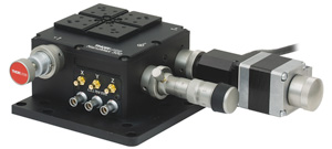
The DRV208 Modular Stepper Motor Actuator is designed to be used with our 3-axis and 6-axis NanoMax™ flexure stages. The M22 x 0.75 threaded flange interfaces directly with the NanoMax stage, making it easy to select an actuator for each axis based on the user's requirements. Using the MCA1 or MCA2 quick-connect adapters, this actuator can also be fitted to a stage with standard Ø3/8" or Ø10 mm mounting clamps, respectively. Additionally, the DRV208 drive is compatible with the DRV120 piezo drive, which adds 20 µm of electronically controlled piezo-actuated travel.
This actuator features an 8 mm travel range and is capable of speeds up to 5 mm/s. The powerful stepper motor driver has a maximum force of 180 N.
The knurled knob on the rear shaft of the motor can function as a manual adjuster when the actuator is powered down. Note that in an open-loop system, manually adjusting the actuator position will desynchronize the actuator from the position display in the control software. This can be corrected by homing the actuator back to its original zero position, which should be done immediately upon powering up the actuator. The knob also serves as an inertial damper which absorbs vibrations from the stepper motor.
A 500 mm (19.7") cable with a 15-pin D-type connector is attached to the unit to connect the stepper motor to a controller. The unit also comes with a 3 m (9.8 ft) extension cable (item # PAA613). If a shorter cable is needed, the 1 m (3.3 ft) PAA612 cable is available separately.
Click to Enlarge
The DRV208 can be installed on a 3-axis NanoMax stage.
How to Calculate the Linear Displacement per Microstep
The stepper motor used in the DRV208 actuator has 200 full steps per revolution of the motor. Each full step is broken down into 2048 microsteps. There are 409,600 microsteps per revolution of the motor when using the BSC201 controller. The end result is the leadscrew advancing by 0.5 mm. To calculate the linear displacement of the actuator microstep, use the following:
409,600 microsteps per revolution of the lead screw
The linear displacement of the lead screw per microstep is:
0.5 mm / 409,600 = 1.2 x 10⁻⁶ mm
To calculate the linear displacment for a full step, substitute 409,600 with 200.
Pin Diagram

High-Density D-Type Male 15 Pin Connector
Connector Pin Out
| Pin | Description | Pin | Description |
|---|---|---|---|
| 1 | Limit Switch 0 V | 9 | For Future Use |
| 2 | Limit Switch 0 V | 10 | +5 V |
| 3 | CW Limit Switch | 11 | - |
| 4 | Motor Phase B -ve | 12 | - |
| 5 | Motor Phase B +ve | 13 | +5 V |
| 6 | Motor Phase A -ve | 14 | - |
| 7 | Motor Phase A +ve | 15 | Ground |
| 8 | - | - | - |

Click to Enlarge
High-Density D-Type Male 15 Pin Connector
| Posted Comments: | |
guanghai zhang
(posted 2020-05-03 09:19:19.12) Hellow, can this modtor be controler by BCS101, the last generation controlor?
Best,
Weili DJayasuriya
(posted 2020-05-05 04:39:03.0) Thank you for your inquiry. Unfortunately these new motor types are not implemented in our legacy firmware used with BCS101. Sorry alfred
(posted 2016-09-10 13:00:27.96) Dear Sir:
I come from Chroma ATE Inc.
I have some question for this apt™ Stepper Motor Controllers Type:BSC203
with Motor Type :DRV001(see on the motor's connecter)
1.I'd like to know device unit about the motor: (nm/Pulse?)
According to ThorLab official specification value:
a.Minimum Incremental Movement:60nm/pulse.Does device unit?
b.Lead Screw Pitch:0.5mm.Does express motor rotation one circle forward 0.5mm?
c.Microsteps per Revolution of Leadscrew:Does express motor rotation one circle need 409600pulse?
So (Lead Screw Pitch/Microsteps per Revolution of Leadscrew)=Minimum Incremental Movement,but 1.2nm is not equal 60nm ,why?
2.Kinesis software(Actuator set APT600L X Axis)
a.Step Size=0.5mm: motor rotation one circle forward 0.5mm? but autaul half circle I see.
b.Travel:8mm ,but I could move 12 mm (show on the current device postion).
Does I configuration error?
Thank you. bwood
(posted 2016-09-12 11:09:51.0) Response from Ben at Thorlabs: Thank you for your feedback. I believe this relates to the conversion between microsteps to real world units. For the DRV001 connected to the BSC203, 1mm equates to 819200µs. I will be in direct contact with you so I can gather more details on your system, and troubleshoot you Kinesis issue in more detail. alfred
(posted 2016-09-09 13:13:17.31) Dear Sir:
I come from Chroma ATE Inc.
I have some question for this apt™ Stepper Motor Controllers Type:BSC203
with Motor Type :8 mm Travel Stepper Motor Actuator
As I use Win32 development(refernece ThorLab exmaple code),set velocity=3838090,position=1715200,Acceleration=2253,Motor vibration occurs,(unit:device unit)
but use Kinesis's APP(Version:1.7.0.0),set velocity=2.5,position=10,Acceleration=2,Motor move smooth,(unit:mm)
1.I'd say that this is not the exact setting we wanted on Win32 code.
2.What number is the Minimum Incremental Movement?
Thank you. bwood
(posted 2016-09-12 08:36:18.0) Response from Ben at Thorlabs: Thank you for your feedback. The answers to these questions will depend on the specific method you are using to control your BSC203, and the system you are trying to build. We will be in direct contact to get further details on your setup and to discuss how to control the BSC203. jjurado
(posted 2011-03-22 09:46:00.0) Response from Javier at Thorlabs to benju: Thank you for contacting us with your request. The DRV001 actuators are not compatible with the T-Cube controllers, as they require a higher current input in order to be operated. I will contact you directly for further support. benju
(posted 2011-03-22 01:53:48.0) can this be operated with a t-cube stepper controller as well? klee
(posted 2009-09-24 10:02:13.0) A response from Ken at Thorlabs to jean-thomas.landry: No, the drawing is not showing it at maximum extension. The minimum length is 134mm and the maximum length is 142mm. jean-thomas.landry
(posted 2009-09-23 11:18:40.0) good morning,
Is the pdf drawing of drv001 showing it at maximum extension?
regards, |

Required Controller:
KIM001 or KIM101
- KIM001: Single-Channel Output
- KIM101: Four Output Channels, Capable of Multi-Channel Operation
- Standalone Control via Top Panel or PC Control via USB
- Voltage Output from 85 V to 125 V
| Item #a | MPIA10 | PIAK10 | ||
|---|---|---|---|---|
| Travel | 10 mm (0.39") | |||
| Typical Step Sizeb,c | 10 - 30 nm (Typ.), ≤30 nm (Max) | |||
| Step Size Adjustabilityd | Up to 30% | |||
| Max Step Frequency | 2 kHz | |||
| Backlash | None | |||
| Max Active Preload | 13 Ne | 30 Nf | ||
| Typical Angular Resolutiong | Ø1/2" Mirror Mounts: <1 μrad | Ø1" Mirror Mounts: 0.5 μrad Ø2" Mirror Mounts: 0.3 μrad |
||
| Recommended Max Axial Load Capacityh |
N/A | 2.5 kg (5.5 lbs) | ||
| Speed (Continuous Stepping)b,c |
1.2 - 3.6 mm/min (Typ.), ≤3.6 mm/min (Max) | |||
| Drive Screw | 6-80 Thread, Hard PVD Coated | 1/4"-80 Thread, Hard PVD Coated | ||
| Motor Type | Piezoelectric Inertia | |||
| Mounting Feature | 3/16"-100 Thread with Lock Nut |
1/4"-80 Thread with Lock Nut | ||
| Operating Temperature | 10 to 40 °C (50 to 104 °F) | |||
| Dimensions | 48.9 x 21.4 x 14.6 mm (1.93" x 0.84" x 0.57”) |
72.9 x 31.5 x 17.0 mm (2.87" x 1.24" x 0.67”) |
||
| Cable Length | 1.0 m (3.28') | |||
| Connector | SMC, Female | |||
| Required Controlleri | KIM001 or KIM101 | |||
Features
- 1/4"-80 or 3/16"-100 Threaded Barrel Versions for Compatibility with Kinematic Mounts or Cage System Optic Mounts
- Compact Design
- MPIA10: 21.4 mm x 14.6 mm (W x H)
- PIAK10: 31.5 mm x 17.0 mm (W x H)
- Typical Step Size Up to 30 nm
- Manual Adjustment via Knob on Adjuster Screw
- Ideal for Set-and-Hold Applications that Require High-Resolution Relative Positioning
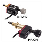
Thorlabs' 10 mm Piezoelectric Inertia Actuators provide high-resolution linear motion control with a 10 mm piezo translation range in compact packages. The MPIA10 and PIAK10 actuators can support preloads up to 13 N and 30 N, respectively, with no backlash. The step size can be adjusted up to 30% to a maximum of approximately 30 nm using the KIM001 or KIM101 Controller and Kinesis® software. However, due to the open-loop design, piezo hysteresis, and application conditions such as the direction of travel, the achieved step size of the system can vary by up to 20% and is not normally repeatable. An external feedback system will need to be used to overcome this variance.
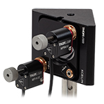
The MPIA10 actuator features a 3/16"-100 threaded barrel, which provides compatibility with many of our Ø1/2" kinematic mounts and optic mounts for 30 mm or 60 mm cage systems. The PIAK10 actuator includes a 1/4"-80 threaded barrel and is compatible with many of our Ø1" and Ø2" kinematic mounts. We also offer 13 mm, 25 mm, and 50 mm actuators with Ø3/8" (Ø9.525 mm) barrels that can be used to drive our translation stages with a Ø3/8" mounting clamp.
The actuators are self-locking when at rest and when there is no power supplied to the piezo, making the actuators ideal for set-and-hold applications that require nanometer resolution and long-term alignment stability. Manual adjustments can be made using the knob on the adjuster screw, as long as the piezo is not actively translating the screw; the knob is also compatible with 5/64" (2.0 mm) hex keys. The control cable of the PIAK10 actuator can be adjusted up to 110° for space-constrained applications (click here to enlarge).
Powered by discrete piezo stacks, the actuators can operate at a maximum speed of up to 3.6 mm/minute. The design of the piezo motor will rotate the tip of the lead screw during translation. Please note that the "slip-stick" nature of these devices uses very short pulse widths and continuous stepping of the actuator will result in an audible noise at a typical level of 60 to 70 dB. For information on the design of our piezo inertia "slip-stick" motor actuators, please see the complete presentation here.
Required Controller
A KIM001 or KIM101 Controller is required to operate our piezo inertia actuators. These drivers have an internal signal generator capable of sending sub-millisecond pulses with tunable amplitudes from 85 V to 125 V. Each actuator has an integrated 1.0 m cable; 1.5 m SMC extension cables (Item # PAA101) and male-to-male SMC adapters (Item # T5026) are also available. Note: Due to the capacitance of the cables, the total length of the control cable should not exceed 2.5 m. For more information, please see the full web presentation.
Click to Enlarge
KCB1(/M) 30 mm Cage-Compatible, Right-Angle Kinematic Mirror Mount with MPIA10 Actuators Attached
(Each Sold Separately)
| Posted Comments: | |
Marco Baruzzo
(posted 2024-10-22 12:33:59.433) Is PIAK10 compatible with K6XS? spolineni
(posted 2024-10-29 11:38:00.0) Thank you for reaching out with your inquiry. The K6XS mount features 1/4"-80 adjuster screws for pitch, yaw, and z-axis adjustments, and 3/16"-100 screws for x- and y-axis adjustments. The PIAK10 actuator, with its 1/4"-80 threaded barrel, is well-suited for the pitch, yaw, and z-axis adjustments on the K6XS. For x- and y-axis adjustments, we recommend the MPIA10 actuator, as its 3/16"-100 threaded barrel is compatible with those adjustments. I’ll be in touch to discuss your specific requirements and provide any further assistance you may need. Filip Munz
(posted 2019-08-20 00:43:57.353) Is this Piezo Inertia Actuator (PIAK10) suitable for high vacuum (cca 0.5 mtorr)? Or can we use rather integrated optic mount like KC1-P? The purpose is a sample adjustment in the chamber.
Can you provide also a suitable feedthrough (ideally with KF40 dimensions)? rmiron
(posted 2019-08-20 05:31:14.0) Response from Radu at Thorlabs: Hello Filip. Unfortunately, PIAK10 is completely unsuitable for vacuum applications. However, we are very seriously looking into expanding our range of vacuum-compatible products. I will relay your feedback internally in the hope that it will accelerate the process. In the meantime, you could use POLARIS-K1S2P or POLARIS-K1S3P which are piezo-driven, vacuum compatible, 1" mounts. The Polaris line also contains vacuum-compatible posts. If longer travel ranges are required, you could use our Z812V or Z812BV vacuum-compatible actuators.
With regards to feedthroughs, we only offer KF16 & KF25 ones on our website (https://www.thorlabs.com/newgrouppage9.cfm?objectgroup_id=12861). However, we could offer KF40 ones as a custom item. If you would like to order such custom feedthroughs, please contact your local technical support team. Jin Ic Kim
(posted 2019-03-28 23:06:49.767) When I use two PIAK10 in KM100 mirror mount, contact point of one out of two hole is not surface, so there is damage occurs at the tip of actuator as the tip rotates.
The other comment is that the actuator seems not return its position when I start at 0 to 20000, then send signal to return 0, sometimes big deviation I have. I'm doing wrong? user
(posted 2019-04-03 07:31:30.0) Response from Arunthathi at Thorlabs: Thanks for your query. I have contacted you directly requesting for further information to troubleshoot the issue |

Required Controller:
KIM001 or KIM101
- KIM001: Single-Channel Output
- KIM101: Four Output Channels, Capable of Multi-Channel Operation
- Standalone Control via Top Panel or PC Control via USB
- Voltage Output from 85 V to 125 V
Click for Details
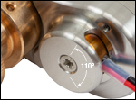
The flying lead can be adjusted up to 110° for space-constrained applications.
Features
- Compact Design: 31.5 mm x 17.0 mm (W x H)
- 20 nm Typical Step Size
- Manual Adjustment via Knob on Adjuster Screw
- Rated Down to 10-6 Torr
- 125 V Maximum Operating Voltage
- 1/4"-100 Mounting Thread for Compatibility with KS1TV Ø1" Mirror Mount
- Ideal for Set-and-Hold Applications that Require High-Resolution Relative Positioning
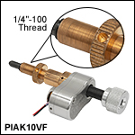
Thorlabs' PIAK10VF Vacuum-Compatible Piezoelectric Inertia Actuator is rated down to 10-6 Torr operation and provides high-resolution linear motion control with a long piezo translation range in a compact, vacuum-compatible package. It can support loads up to 2.5 kg (5.51 lbs) and preloads up to 30 N with typical step size ranging from 10 nm to 30 nm and no backlash. The step size can be adjusted up to 30% to a maximum of approximately 30 nm using a compatible controller and the Kinesis® software. However, due to the open-loop design, piezo hysteresis, and application conditions such as the direction of travel, the achieved step size of the system can vary by up to 20% and is not normally repeatable. An external feedback system will need to be used to overcome this variance.
The actuator is self-locking when at rest and when there is no power supplied to the piezo, making the actuator ideal for set-and-hold applications that require nanometer resolution and long-term alignment stability. Manual adjustments can be made using the knob on the adjuster screw, as long as the piezo is not actively translating the screw; the knob is also compatible with 5/64" (2.0 mm) hex keys.
This actuator has a 1/4"-100 threaded barrel that can be mounted to the KS1TV mirror mount or other mounts with non-matched 1/4"-100 actuators. Note that the PIAK10VF actuator is not compatible with Polaris® mounts that use 1/4"-100 adjusters. These mounts require a specific actuator ball size and tip design to ensure that the ball contact is centered on the sapphire end stone and that there is proper screw clearance during full translation. In the case of the PIAK10VF actuator, the side of the screw, rather than the ball tip, will contact the sapphire end stone and, as a result, the actuator should not be used with Polaris mounts. We also offer 13 mm, 25 mm, and 50 mm actuators with Ø3/8" (Ø9.525 mm) barrels that can be used to drive our translation stages with a Ø3/8" mounting clamp.
Each actuator has an integrated 0.75 m flying lead, plus 1.0 m of cored cable for wiring outside the vacuum chamber. The flying leads and cored cable lengths can be cut down as needed, but the total length (inside and outside) should not exceed 2.0 m. As shown in the image above, the flying lead for each actuator can be rotated up to 110° for space-constrained applications.
Powered by a 10 mm long discrete piezo stack, the actuator can operate at speeds of up to 3.6 mm/minute. The design of the piezo motor will rotate the tip of the lead screw during translation. For information on the design of our piezo inertia "slip-stick" motor actuators, please see the complete presentation here.
| Item #a | PIAK10VF | |||
|---|---|---|---|---|
| Travel | 10 mm (0.39") | |||
| Step Sizeb,c | 10 - 30 nm (Typ.), ≤30 nm (Max) | |||
| Step Size Adjustabilityd | Up to 30% | |||
| Max Step Frequency | 2 kHz | |||
| Backlash | None | |||
| Max Active Preloade | 30 N | |||
| Typical Angular Resolution | KS1TV Ø1" Mirror Mount: 0.5 μrad | |||
| Recommended Max Axial Load Capacityf |
2.5 kg (5.5 lbs) | |||
| Speed (Continuous Stepping)b,c |
1.2 - 3.6 mm/min (Typ.), ≤3.6 mm/min (Max) | |||
| Drive Screw | 1/4"-80 Thread, Hard PVD Coated | |||
| Motor Type | Piezoelectric Inertia | |||
| Mounting Feature (Auxiliary) |
1/4"-100 Thread with Lock Nutg (Ø3/8" [Ø9.525 mm] Barrel) |
|||
| Operating Temperature | 5 to 40 °C | |||
| Max Bakeout Temperature | 130 °C | |||
| Dimensions | 77.7 mm x 31.5 mm x 17.0 mm (3.06" x 1.24" x 0.67") |
|||
| Cable Length | 0.75 m (2.46 ft) Flying Lead for Vacuum, 1.0 m (3.3 ft) of Cored Cable for Wiring Outside Chamber |
|||
| Connector | SMC, Female | |||
| Vacuum Rating | 10-6 Torr | |||
| Required Controllerh | KIM001 or KIM101 | |||
Required Controller
A KIM001 or KIM101 Controller is required to operate our PIAK10VF Piezo Inertia Actuator; the actuator cannot be operated using a standard piezo controller. These drivers have an internal sawtooth voltage signal generator capable of sending sub-millisecond pulses (steps) with controllable amplitudes from 85 V to 125 V.
For more information, please see the full web presentation.
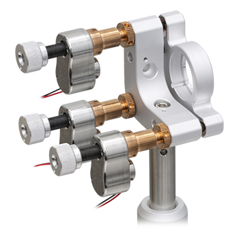
Click to Enlarge
Three PIAK10VF Inertia Actuators Being Used in Place of the
1/4"-100 Adjustment Screws in our KS1TV Mirror Mount
(Mount Sold Separately)
| Posted Comments: | |
| No Comments Posted |

Features
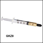
- 1.5 cc Syringe of Apiezon 100 Grease
- Convenient, Inexpensive Package that Reduces Waste
- Prolongs Lifetime of Actuator
- Ready to Dispense
- Vacuum Compatible to 10-9 Torr
This Apiezon grease has excellent anti-seize properties. It contains PTFE for maximum lubricity and is ideal for re-lubricating the lead screw threads of our ZST, ZFS, and Z9 series actuators. It is supplied in a syringe for easy application and is recommended both for general use and for vacuum applications down to
Note: It is recommended that the lead screw and end ball of the Z9, ZFS, and ZST actuators are lubricated every 10,000 cycles or whenever a squeaking noise is heard during motion.
| Posted Comments: | |
| No Comments Posted |

Thorlabs' DRV, ZST, and ZFS Stepper Motor Actuators, as well as our Z9 DC Servo Motor Actuators, come with cables for connecting to the required controllers. Thorlabs also offers separate cables that may be used as extension cables.
Stepper Motor Cables
Thorlabs offers a variety of cables to support several stepper motor actuator and controller combinations. Supported stepper motors include our ZST, ZFS, and DRV actuators; supported controllers include our BSC benchtop controllers, our KST201 K-Cube™ Controller, and our MST602 Rack Control Module. In order to see which cable is compatible with a given combination of stepper motor and controller, please see the table below. The pin assignment for each cable is given in the Pin Diagrams tab. Please note that these cables cannot be used with motors and controllers that do not match their pin assignment, even if the connectors are the same.
DC Motor Cables
The PAA632 is a 2.5 m cable for our Z9 series of DC motor actuators. This cable is intended to be used with the KDC101 K-Cube DC Servo Motor Controller. The pin assignment for this cable is given in the Pin Diagrams tab. Although it uses a 15-pin connector, this cable is not compatible with any of our stepper motors.

 |
|
PAA612 and PAA613 Stepper Motor Cables
DA15 Male D-Type to DE15 Female D-Type
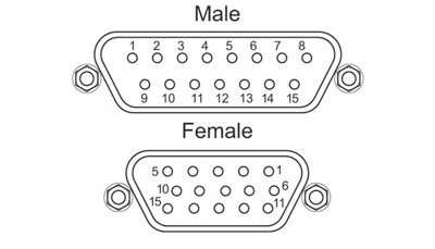
| DA15 Male Pin | DE15 Female Pin | Description |
|---|---|---|
| 11 and 12 | 1 | Limit Switch Ground |
| 10 | 2 | Reverse Limit Switch |
| 9 | 3 | Forward Limit Switch |
| 7 | 4 | Motor Phase B - |
| 14 | 5 | Motor Phase B + |
| 8 | 6 | Motor Phase A - |
| 15 | 7 | Motor Phase A + |
| 6 | 9 | Reserved for Future Use |
| 5 | 13 | 5 V |
PAA632 DC Servo Motor Cable
DE15 Male D-Type to DE15 Female D-Type

| DE15 Male Pin | DE15 Female Pin | Description |
|---|---|---|
| 1 | 1 | Ground |
| 2 | 2 | Forward Limit Switch |
| 3 | 3 | Reverse Limit Switch |
| 5 | 5 | Motor - |
| 7 | 7 | Motor + |
| 10 | 10 | 5 V Encoder Supply |
| 11 | 11 | Encoder Channel A |
| 13 | 13 | Encoder Channel B |
PAA614 Stepper Motor Cable
DE15 Male D-Type to DE15 Female D-Type

| DE15 Male Pin | DE15 Female Pin | Description |
|---|---|---|
| 1 | 1 | Ground |
| 2 | 2 | CCW Limit Switch |
| 3 | 3 | CW Limit Switch |
| 4 | 4 | Motor Phase B - |
| 5 | 5 | Motor Phase B + |
| 6 | 6 | Motor Phase A - |
| 7 | 7 | Motor Phase A + |
| 10 | 10 | +5 VDC |
| 15 | 15 | Ground |
| Posted Comments: | |
| No Comments Posted |
 Products Home


 Zoom
Zoom




 10 mm (0.39") or Less Travel